
Slab conveying device with variable track

A conveying device and variable technology, applied in the field of mechanical transmission, can solve the problems of increasing the number of equipment, configuring equipment investment costs, increasing operating costs, and long transportation time, and achieving the effects of saving conveying time, reducing energy, and low operating costs.

Active Publication Date: 2016-09-28
CHINA NAT HEAVY MACHINERY RES INSTCO
View PDF6 Cites 0 Cited by
  • Summary
  • Abstract
  • Description
  • Claims
  • Application Information

AI Technical Summary

Problems solved by technology

The currently used steel billet conveying devices are steel pusher, hoist and conveyor. The three conveying steps lead to a relatively long transportation time, which exceeds the temperature drop requirement and is lower than 850 degrees. Therefore, after the transportation is completed and before rolling, Increase heating and holding furnace
This process not only increases the number of equipment, configuration, and equipment investment costs, but also wastes energy and increases operating costs.

Method used


Image

  • Slab conveying device with variable track
  • Slab conveying device with variable track
  • Slab conveying device with variable track

Examples


Embodiment Construction

[0015] The present invention will be described in further detail below in conjunction with the accompanying drawings.

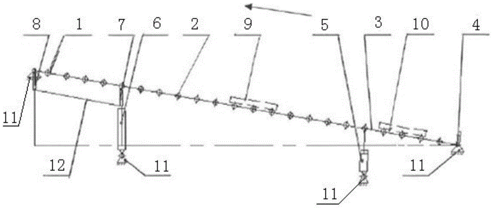
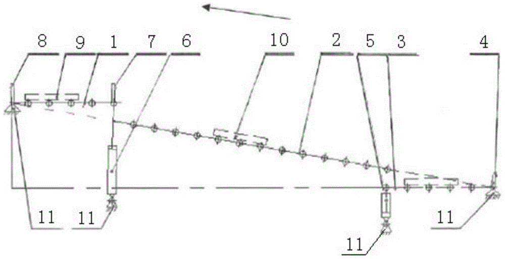
[0016] see figure 1 , a slab conveying device with a variable track, including a fixed middle-end conveying track 2, the middle-end conveying track 2 is arranged obliquely, and the front and rear ends of the middle-end conveying track 2 are respectively connected with a front-end conveying track 1 and a rear-end conveying Track 3, the front end of the front end delivery track 1 is fixed on the frame 11, and the second push cylinder 6 is connected to the bottom of the rear end. The front ends of 2 are docked to form a plane. The rear end of the rear conveying track 3 is fixed on the frame 11, and the bottom of the front end is connected with the first push cylinder 5. When the first push cylinder 5 is in the extended state, the rear end conveys The front end of the track 3 is docked with the rear end of the middle conveying track 2 to form a plane. A fixed b...


PUM


Abstract

The invention discloses a slab conveying device with a variable track. The slab conveying device comprises a fixedly arranged middle-end conveying track, wherein the middle-end conveying track is inclined; the front end and the rear end of the middle-end conveying track are respectively connected with a front-end conveying track and a rear-end conveying track; the front end of the front-end conveying track is fixed on a stander; the lower side at the rear end of the front-end conveying track is connected with a second push cylinder; when the second push cylinder is in a contraction state, the rear end of the front-end conveying track is butted with the front end of the middle-end conveying track to form a plane; the rear end of the rear-end conveying track is fixed on the stander; the lower side of the rear-end conveying track is connected with a first push cylinder; when the first push cylinder is in an extending state, the front end of the rear-end conveying track is butted with the rear end of the middle-end conveying track to form a plane; oil cylinders are used for pushing the conveying tracks, so that the conveying tracks can be freely converted between a horizontal state and an inclined state; the number of the conveying steps is small; lifting and conveying can be synchronously realized; the conveying time is effectively shortened; the slab conveying device has the characteristics of low cost, energy conservation and high efficiency.

Description

technical field [0001] The invention belongs to the technical field of mechanical transmission, and in particular relates to a slab conveying device with a variable track. Background technique [0002] Limited by the location, size and process requirements of the continuous casting equipment and rolling equipment, the continuous casting machine and rolling equipment are generally tens of meters or even hundreds of meters apart in position, and there is a height difference of several meters. However, the process requires that after the steel billet is cut from the flame cutting part of the continuous casting machine, the starting rolling temperature before rolling should generally not be lower than 850 degrees. The currently used billet conveying devices are steel pusher, hoist and conveyor. The three conveying steps lead to a relatively long transportation time, which exceeds the temperature drop requirement and is lower than 850 degrees. Therefore, after the conveyance is c...

Claims


Application Information

Patent Timeline
Patent Type & Authority Patents(China)
IPC IPC(8): B22D11/128
CPCB22D11/1284
Inventor 徐鸿钧李国莉
Owner CHINA NAT HEAVY MACHINERY RES INSTCO
Learn More