Illumination light control circuit for eye-ground photography
A light control and circuit technology, applied in ophthalmoscopes, eye testing equipment, applications, etc., can solve the problems of damage to the retina, discomfort to the human eye, and high cost, and achieve the goal of reducing irritation, reducing production costs, and improving clarity. Effect
- Summary
- Abstract
- Description
- Claims
- Application Information
AI Technical Summary
Problems solved by technology
Method used
Image

Examples
Embodiment 1
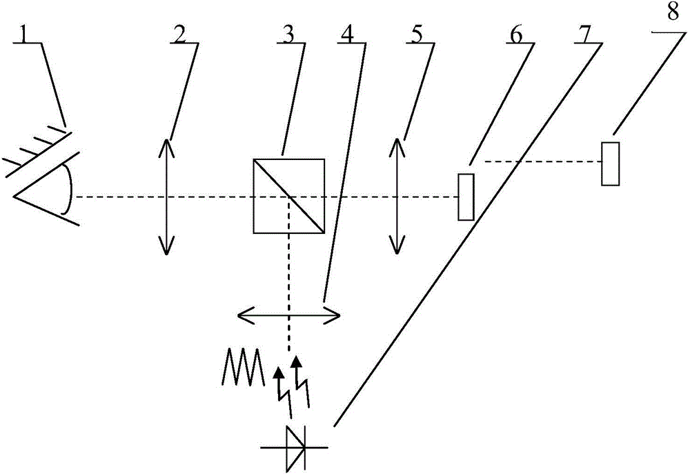
[0026] see figure 1 , an illumination light control circuit for fundus photography, comprising: an eyepiece and an objective lens 2, a semi-transparent half-reflective prism 3, an illumination lens group 4, an imaging objective lens 5, an image sensor 6, an LED lighting lamp 7 and a computer 8, wherein , the eyepiece and the objective lens 2, the half-reflective prism 3, the imaging objective lens 5 and the image sensor 6 are arranged in sequence, and an illuminating lens group 4 is arranged between the half-reflective prism 3 and the LED lighting lamp 7;
[0027] Among them, the LED lighting lamp 7 is driven by a triangular wave or sawtooth wave electrical signal to generate a beam of triangular wave or sawtooth waveform illumination light, and the triangular wave or sawtooth waveform illumination light sequentially passes through the illumination lens group 4, the semi-transparent and half-reflective prism 3, the eyepiece and the objective lens 2 irradiates the fundus of the...
Embodiment 2
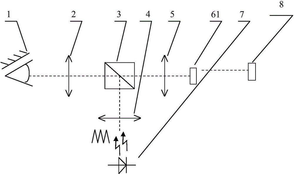
[0042] see figure 2 , an illumination light control circuit for fundus photography, the difference between the illumination light control circuit and Embodiment 1 is that the image sensor 6 is specifically a CCD image sensor 61, and the illumination light control circuit includes: an eyepiece and an objective lens 2, a translucent Semi-reflective prism 3, illumination lens group 4, imaging objective lens 5, CCD image sensor 61, LED lighting lamp 7 and computer 8, wherein, connect eyepiece and objective lens 2, semi-transparent half-reflective prism 3, imaging objective lens 5 and CCD image sensor 61 Arranged in sequence, an illuminating lens group 4 is arranged between the half-transparent and half-reflecting prism 3 and the LED illuminating lamp 7;
[0043] Among them, the LED lighting lamp 7 is driven by a triangular wave or sawtooth wave electrical signal to generate a beam of triangular wave or sawtooth waveform illumination light, and the triangular wave or sawtooth wave...
Embodiment 3
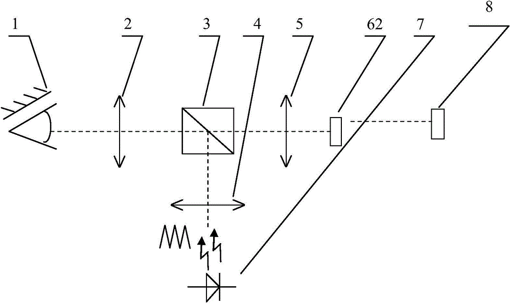
[0047] see image 3 , an illumination light control circuit for fundus photography, the difference between the illumination light control circuit and embodiment 1 is that the image sensor 6 is specifically a CMOS image sensor 62, and the illumination light control circuit includes: an eyepiece and an objective lens 2, a translucent Semi-reflective prism 3, lighting lens group 4, imaging objective lens 5, CMOS image sensor 62, LED lighting lamp 7 and computer 8, wherein, connect eyepiece and objective lens 2, semi-transparent half-reflective prism 3, imaging objective lens 5 and CMOS image sensor 62 Arranged in sequence, an illuminating lens group 4 is arranged between the half-transparent and half-reflecting prism 3 and the LED illuminating lamp 7;
[0048] Among them, the LED lighting lamp 7 is driven by a triangular wave or sawtooth wave electrical signal to generate a beam of triangular wave or sawtooth waveform illumination light, and the triangular wave or sawtooth wavefo...
PUM
 Abstract
Description
Claims
Application Information
 - R&D
- Intellectual Property
- Life Sciences
- Materials
- Tech Scout
- Unparalleled Data Quality
- Higher Quality Content
- 60% Fewer Hallucinations
Browse by: Latest US Patents, China's latest patents, Technical Efficacy Thesaurus, Application Domain, Technology Topic, Popular Technical Reports.
© 2025 PatSnap. All rights reserved.Legal|Privacy policy|Modern Slavery Act Transparency Statement|Sitemap|About US| Contact US: help@patsnap.com