Data sending and receiving method
A technology for data transmission and reception, data application in data exchange network, data exchange details, data exchange through path configuration, etc. It can solve the problem of not building a master-slave relationship between devices, and achieve the reduction of times, reliable data transmission, and power suppression. The effect of consumption
- Summary
- Abstract
- Description
- Claims
- Application Information
AI Technical Summary
Problems solved by technology
Method used
Image

Examples
no. 1 Embodiment approach
[0039] First, the data transmission and reception method according to the first embodiment of the present invention will be described.
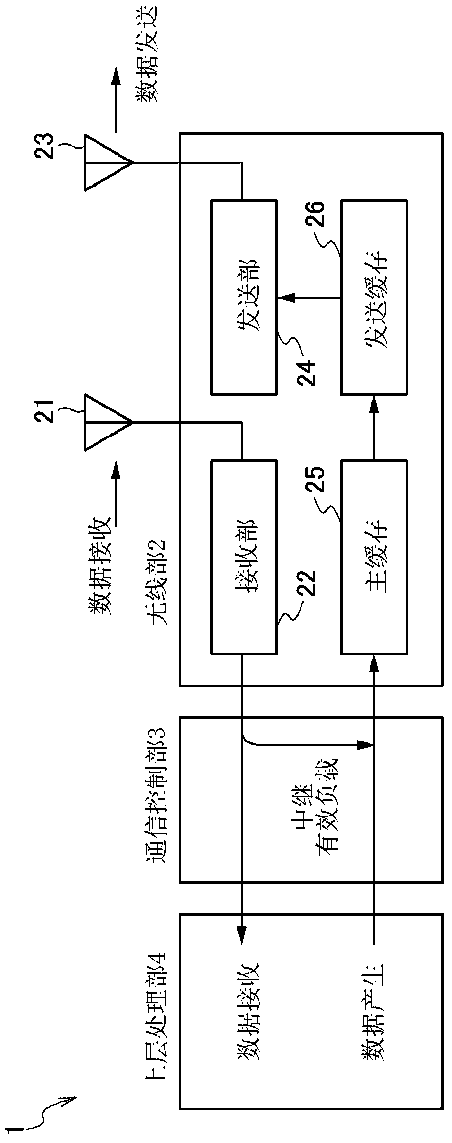
[0040] figure 1 It is a figure which shows the structure of the node in the data transmission and reception method of embodiment. A node 1 is configured to include a wireless unit 2 , a communication control unit 3 , and an upper layer processing unit 4 . In addition, a node is a general term for devices including FFD and RFD that perform data transmission and reception such as data distribution and relay.
[0041] The wireless unit 2 has a receiving unit 22 for receiving data via a receiving antenna 21, a transmitting unit 24 for transmitting data via a transmitting antenna 23, a main buffer 25 for buffering various data, and a buffer provided between the main buffer 25 and the transmitting unit 24. The transmission buffer 26 temporarily buffers the transmission data transmitted from the main buffer 25 to the transmission unit 24 .
[00...
no. 2 Embodiment approach
[0061] Next, a data transmission and reception method according to a second embodiment of the present invention will be described.
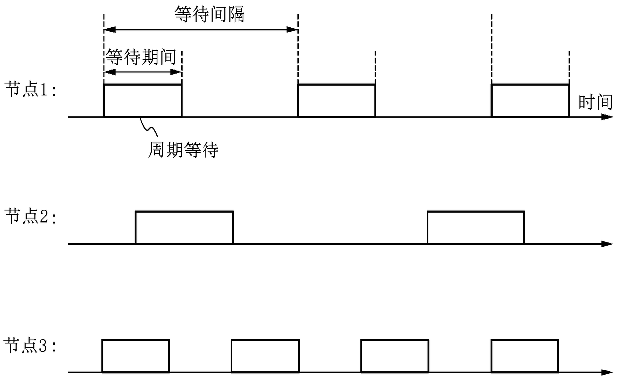
[0062] In the data sending and receiving method of this embodiment, also as figure 2 As shown, similarly to the first embodiment, each node 1 periodically waits for a unique waiting period and a unique interval. Furthermore, the detection method of the surrounding nodes 1 in this embodiment is performed in the same manner as the method in the above-mentioned first embodiment, and a request node and a response node are generated.
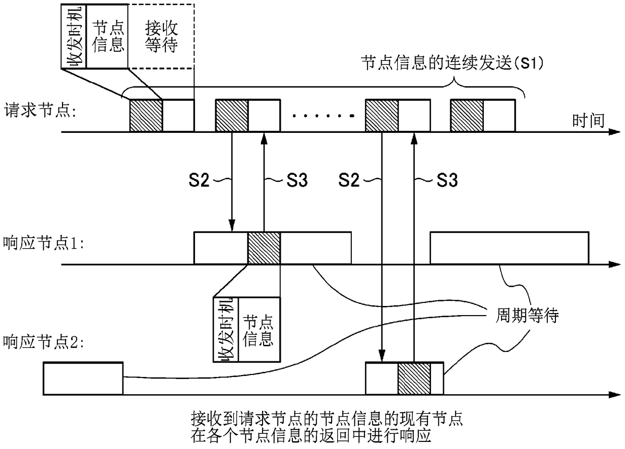
[0063] Next, the state of data transmission and reception performed after the detection of the peripheral nodes will be described below. Figure 5 It is a diagram showing the status of data transmission and reception between nodes 1 in the data transmission and reception method according to the second embodiment of the present invention.
[0064] First, the response node continuously transmits to the request node wai...
no. 3 Embodiment approach
[0071] Next, a data transmission and reception method according to a third embodiment of the present invention will be described.
[0072] In the data sending and receiving method of this embodiment, also as figure 2As shown, similarly to the first embodiment, each node 1 periodically waits for a unique waiting period and a unique interval. Furthermore, the detection method of the surrounding nodes 1 in this embodiment is performed in the same manner as the method in the above-mentioned first embodiment, and a request node and a response node are generated.
[0073] Next, the state of data transmission and reception performed after the detection of the peripheral nodes will be described below. Figure 6 It is a diagram showing the status of data transmission and reception between nodes 1 in the data transmission and reception method according to the third embodiment of the present invention.
[0074] First, the requesting node sends the waiting information request of the re...
PUM
 Abstract
Description
Claims
Application Information
 - Generate Ideas
- Intellectual Property
- Life Sciences
- Materials
- Tech Scout
- Unparalleled Data Quality
- Higher Quality Content
- 60% Fewer Hallucinations
Browse by: Latest US Patents, China's latest patents, Technical Efficacy Thesaurus, Application Domain, Technology Topic, Popular Technical Reports.
© 2025 PatSnap. All rights reserved.Legal|Privacy policy|Modern Slavery Act Transparency Statement|Sitemap|About US| Contact US: help@patsnap.com