
Electronic control apparatus for vehicle and control method for vehicle

a technology of electronic control apparatus and control method, which is applied in the direction of machines/engines, liquid/fluent solid measurement, instruments, etc., can solve the problems of battery waste, difficult to start the next engine operation, and battery charge not being performed, etc., to achieve the effect of suppressing the waste of batteries

Inactive Publication Date: 2005-05-19
HITACHI ASTEMO LTD
View PDF13 Cites 8 Cited by
  • Summary
  • Abstract
  • Description
  • Claims
  • Application Information

AI Technical Summary

Benefits of technology

[0009] The present invention has an object to enable the execution of the process to be performed after an engine operation is stopped, while suppressing the waste of a battery during the engine operation is stopped.

Problems solved by technology

However, since an operation of a dynamo which is driven by the engine is stopped during the stop of engine operation, a battery charge is not performed.
Accordingly, if the leakage diagnosis is performed after the standby until the fuel vapor generation is finished after the engine operation has been stopped, the battery is wasted, and consequently, it becomes hard to start the next engine operation.

Method used


Image

  • Electronic control apparatus for vehicle and control method for vehicle
  • Electronic control apparatus for vehicle and control method for vehicle
  • Electronic control apparatus for vehicle and control method for vehicle

Examples


Embodiment Construction

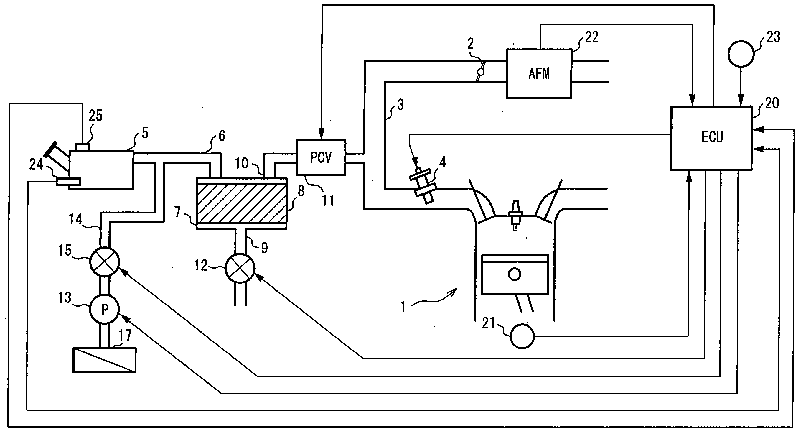
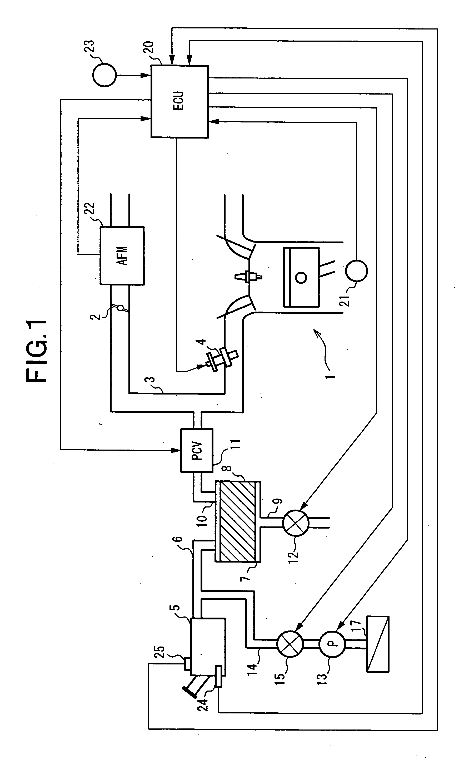
[0018]FIG. 1 shows a system configuration of an engine in an embodiment.

[0019] Engine 1 is a gasoline engine installed in a vehicle (not shown in the figure).

[0020] A throttle valve 2 is disposed in an intake pipe 3 of engine 1, and an intake air amount of engine 1 is controlled by throttle valve 2.

[0021] A fuel injection valve 4 is disposed to an intake port of each cylinder.

[0022] Fuel injection valve 4 is opened based on an injection pulse signal output from an engine control unit 20, to inject fuel.

[0023] Engine 1 is provided with a fuel vapor purge system.

[0024] The fuel vapor purge system is for adsorbing the fuel vapor generated in a fuel tank 5 to a canister 7 via an evaporation passage 6, and for detaching the fuel vapor adsorbed to canister 7, to supply the detached fuel vapor to intake pipe 3 of engine 1.

[0025] Canister 7 is a container filled with the adsorbent 8 such as activated carbon.

[0026] Further, a new air inlet 9 is formed to canister 7, and a purge passa...


PUM

PropertyMeasurementUnit
standby timeaaaaaaaaaa
pressureaaaaaaaaaa
timeaaaaaaaaaa

Abstract

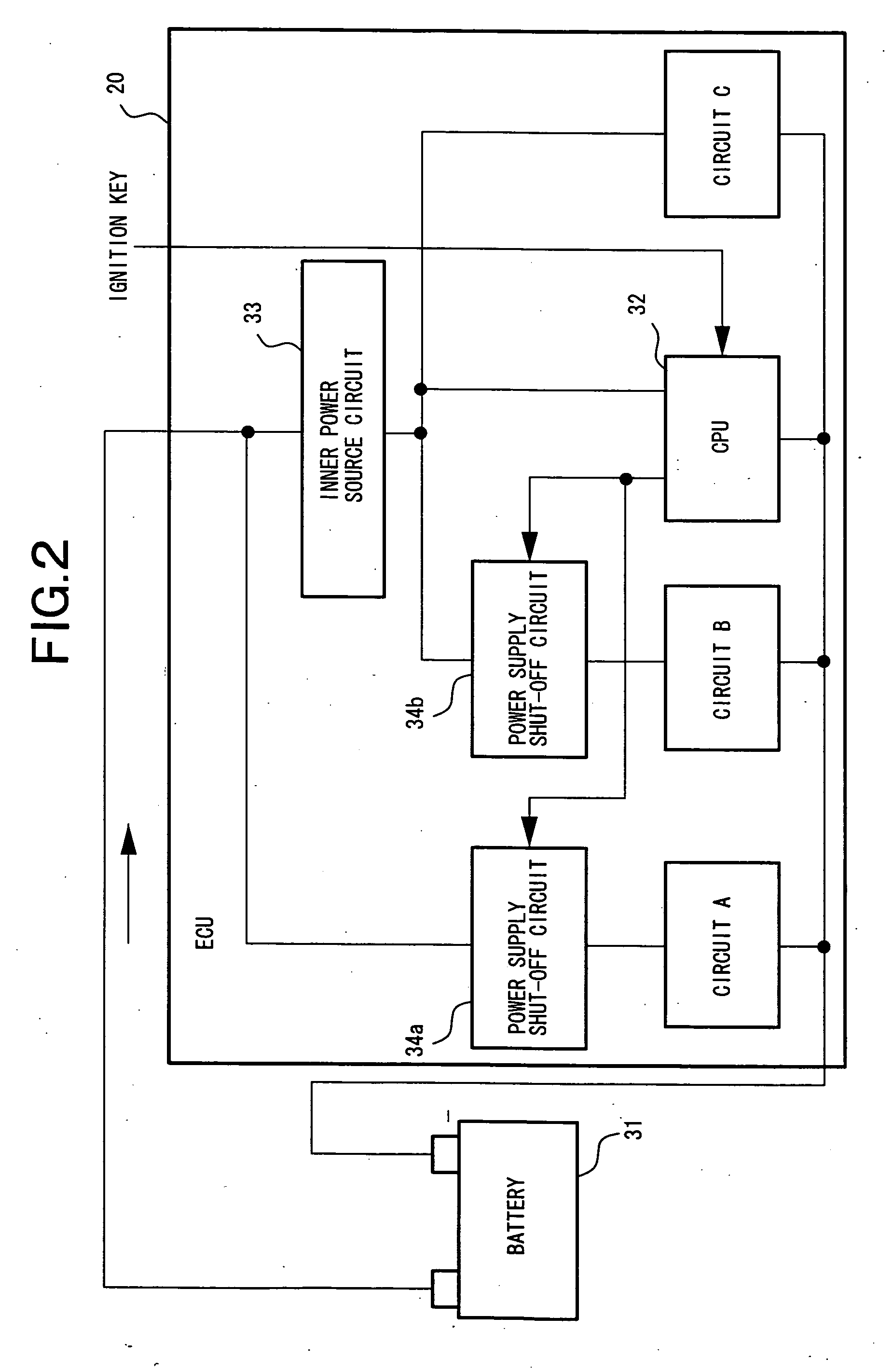
In the case where it is diagnosed whether or not the leakage occurs in a fuel vapor purge system from a standby time has elapsed after an engine operation was stopped, the power supply to processing circuits unnecessary for the leakage diagnosis is shut off, thereby suppressing the power consumption during the engine operation stop.

Description

FIELD OF THE INVENTION [0001] The present invention relates to an electronic control apparatus for a vehicle and a control method for a vehicle, and in particular, to a technique for performing the process, such as the diagnosis or the like, after an operation of an engine is stopped. DESCRIPTION OF THE ART [0002] Japanese Unexamined Patent Publication No. 2003-013810 discloses a diagnosis apparatus for diagnosing whether or not the leakage occurs in a fuel vapor purge system equipped to a vehicle engine. [0003] In this diagnosis apparatus, a diagnosis section in the fuel vapor purge system is shielded by valves after an engine operation has been stopped, and the diagnosis section is supplied with air by an air pump to be pressurized. Then, it is diagnosed whether or not the leakage occurs in the diagnosis section, based on a driving load of the air pump during the pressurization. [0004] In the case where the diagnosis section inclusive of a fuel tank is pressurized by the air pump,...

Claims


Application Information

Patent Timeline
Patent Type & Authority Applications(United States)
IPC IPC(8): F02M25/08
CPCF02M25/0827
Inventor WAKAIRO, MASAHIKO
Owner HITACHI ASTEMO LTD
Learn More