
Flip-flop circuit

A flip-flop, circuit technology, used in logic circuits, electrical components, pulse technology, etc.

Active Publication Date: 2015-07-22
陈祺琦
View PDF3 Cites 25 Cited by
  • Summary
  • Abstract
  • Description
  • Claims
  • Application Information

AI Technical Summary

Problems solved by technology

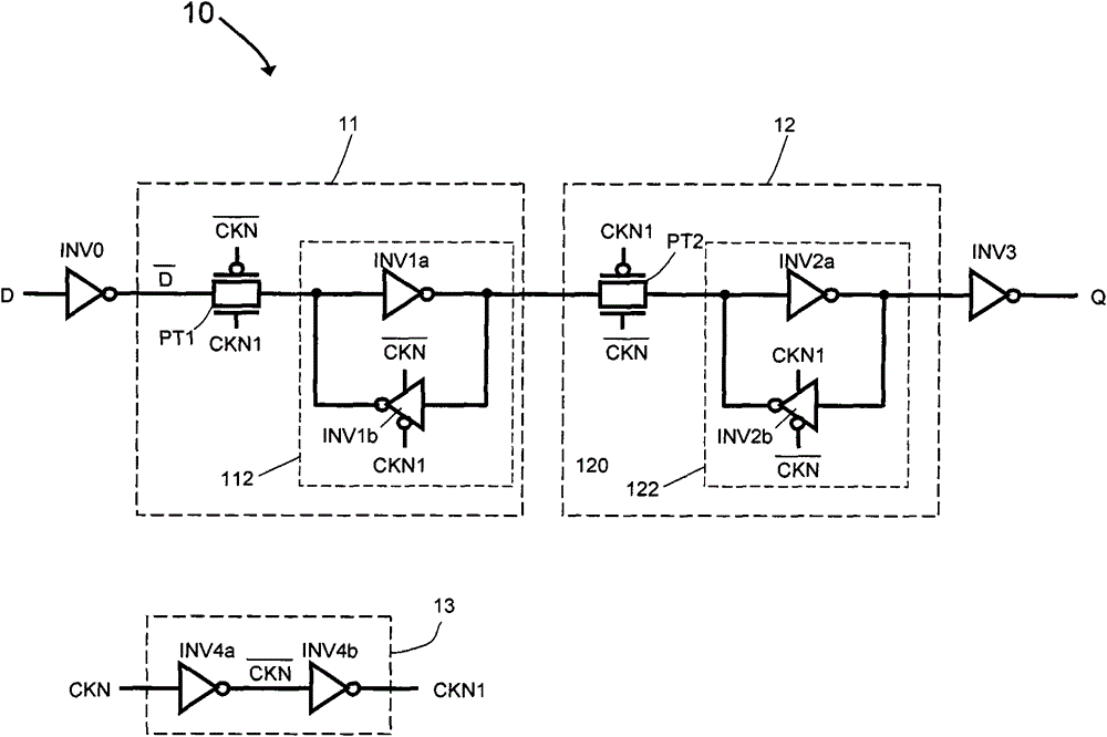
Therefore, regardless of whether the state of the flip-flop changes, as the clock flips, the circuit needs to provide a large amount of power consumption to drive these inverters, transmission gates (or tri-state gates)

Method used


Image

  • Flip-flop circuit
  • Flip-flop circuit
  • Flip-flop circuit

Examples


Embodiment Construction

[0069] The following introduces some of the possible embodiments of the present invention, which are intended to provide a basic understanding of the present invention, but are not intended to identify key or decisive elements of the present invention or limit the scope of protection. It is easy to understand that, according to the technical solution of the present invention, those skilled in the art may propose other alternative implementation manners without changing the essence and spirit of the present invention. Therefore, the following specific embodiments and drawings are only exemplary descriptions of the technical solution of the present invention, and should not be regarded as the entirety of the present invention or as a limitation or restriction on the technical solution of the present invention.

[0070] In order to better understand the progress of the flip-flop circuit of the present invention in terms of power consumption, first a detailed example is given to re...


PUM


Abstract

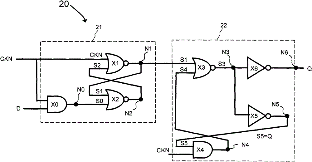
The invention provides a flip-flop circuit, and belongs to the technical field of semiconductor integrated circuits. The flip-flop circuit comprises a master latch and a secondary latch driven by clocking signals with same phases; the master latch comprises a first logic module for selectively and at least performing AND logic processing on an input data signal and the clock signal, a second logic module for at least performing NOR logic processing on the clock signal and an output signal of a third logic module, and the third logic module for selectively and at least performing the NOR logic processing on the output signal of the first logic module and the output signal of the second logic module so as to output a result to the second logic module; the secondary latch comprises a fourth logic module for at least performing the NOR logic processing on the output signal of the second logic module and the output signal of a fifth logic module, and the fifth logic module for at least performing the AND logic processing on the clock signal and an inversion signal of the output signal of the fourth logic module. The flip-flop circuit is low in dynamic power consumption.

Description

technical field [0001] The invention belongs to the technical field of semiconductor integrated circuits (ICs), and relates to a trigger circuit for realizing low power consumption. Background technique [0002] With the increasing integration density of integrated circuits (Integrated Circuit, IC) and the continuous improvement of its clock operating frequency, the power consumption (especially the dynamic power consumption) of the IC has drawn more and more attention. Especially for portable electronic devices, their performance and power consumption are a contradiction. Major manufacturers are constantly improving the performance of electronic devices while reducing their power consumption in order to increase the use time of the limited power of portable electronic devices. The application of various high-performance ICs in portable electronic devices is often limited due to high power consumption. [0003] A flip-flop (Flip-Flop) circuit is a basic functional circuit u...

Claims


Application Information

Patent Timeline
IPC IPC(8): H03K19/094
Inventor 陈祺琦
Owner 陈祺琦
Learn More