
Metal bipolar plate for fuel cell

A metal bipolar plate and fuel cell technology, which is applied to battery electrodes, circuits, electrical components, etc., can solve the problems of complex stamping dies and increasing the thickness of metal double plates

Active Publication Date: 2015-07-22
SHANGHAI SHENLI TECH CO LTD
View PDF5 Cites 7 Cited by
  • Summary
  • Abstract
  • Description
  • Claims
  • Application Information

AI Technical Summary

Problems solved by technology

Among them, the diversion groove on the bipolar plate is stamped and formed by a metal plate. Since the metal bipolar plate is very thin, stamping out various shapes of the diversion fluid channel groove is not only complicated in stamping dies, but also the thickness of the diversion groove is required. It is bound to greatly increase the thickness of the metal double plate

Method used


Image

  • Metal bipolar plate for fuel cell
  • Metal bipolar plate for fuel cell
  • Metal bipolar plate for fuel cell

Examples


Embodiment 1

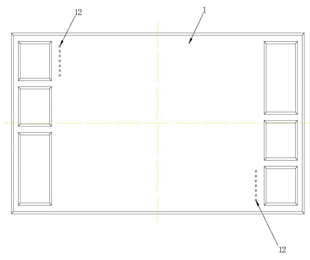
[0024] A metal bipolar plate for a 60kw proton exchange membrane fuel cell, with a length and width of 100×400mm, such as Figure 1~4 As shown, the metal bipolar plate is stamped from two 0.2mm stainless steel metal plates with the same thickness to form a hydrogen pole plate 1 and an oxygen pole plate 2. Both the hydrogen pole plate 1 and the oxygen pole plate 2 are provided with common hydrogen channel openings, and the common Oxygen channel openings, common cooling fluid openings, and sealing grooves are provided along both sides and the sides of the common fluid openings. The sealing grooves are 4mm wide and 0.4mm deep. A 0.4mm thick soft graphite plate in the shape of a straight groove is extruded to form a hydrogen pole plate, and a soft graphite plate with a thickness of 0.4mm that guides the air flow is placed in the cavity formed by stamping on the oxygen pole 2. Oxygen pole plate is formed, and the depth of the cavity of the hydrogen-conducting airflow and the cavity...

Embodiment 2

[0027] The bracket is made of rubber or plastic material, and is pressed and bonded together with the hydrogen pole plate and the oxygen pole plate.

[0028] The three cavities are respectively placed with a porous carbon diffusion layer conductive material without the overall shape of the flow tank, and the thickness is the same as that of the soft graphite sheet. All the other are with embodiment 1.


PUM

PropertyMeasurementUnit
depthaaaaaaaaaa
thicknessaaaaaaaaaa

Abstract

The invention relates to a metal bipolar plate for a fuel cell. The metal bipolar plate is a hydrogen polar plate and an oxygen polar plate which are formed by stamping of two metal plates with the same thickness. The hydrogen polar plate and the oxygen polar plate are both provided with a common hydrogen channel opening, a common oxygen channel opening, a common cooling fluid opening and a seal groove arranged along two sides and each common fluid opening side. A hydrogenstream-guiding conductive diffusion layer material is placed inside a cavity formed by stamping on the hydrogen polar plate, or a groove-shaped conductive material is arranged, so as to form the hydrogen polar plate. An air flow-guiding conducive diffusion layer material is placed inside a cavity formed by stamping on the oxygen polar plate, or a groove-shaped conductive material is arranged, so as to form the oxygen polar plate. The hydrogenstream-guiding cavity and the air flow-guiding cavity have the same depth with the seal groove. The hydrogen polar plate and the oxygen polar plate are folded back to back through a bracket to form the bipolar plate. The backs of the two plates are abutted against a bracket which has the same shape with the whole seal groove so as to make the bipolar plate form three cavities: an upper cavity for guiding hydrogen, a middle cavity for guiding the cooling fluid and a lower cavity for guiding the air. In comparison with the prior art, the metal bipolar plate has a simple structure, and stamping of various fluid groove shapes is not required.

Description

technical field [0001] The invention belongs to the technical field of fuel cells, in particular to a metal bipolar plate for a fuel cell. Background technique [0002] A fuel cell is generally constructed of a plurality of cells, each cell comprising two electrodes (anode and cathode) separated by an electrolyte element and assembled in series with each other to form a fuel cell stack. The electrochemical reaction is achieved by supplying the appropriate reactants to each electrode, ie fuel to one electrode and oxidant to the other, creating a potential difference between the electrodes and thereby generating electrical energy. [0003] In order to supply each electrode with reactants, specific interface elements commonly referred to as "bipolar plates" and arranged on both sides of each individual cell are used. These bipolar plates are usually in the form of a single element placed adjacent to the anode or cathode support. Bipolar plates are an important element of a fu...

Claims


Application Information

Patent Timeline
Patent Type & Authority Applications(China)
IPC IPC(8): H01M4/86
CPCH01M4/8605Y02E60/50
Inventor 胡里清
Owner SHANGHAI SHENLI TECH CO LTD
Learn More