
Method and system for focusing multi-camera module based on near-infrared environment

A multi-camera, near-infrared technology, applied in the field of focusing methods and systems of multi-camera modules, can solve the problems that the test standard cannot be filled, there is no multi-camera comparison and processing, and the focusing operation is complicated.

Active Publication Date: 2015-07-22
NINGBO SUNNY OPOTECH CO LTD
View PDF7 Cites 7 Cited by
  • Summary
  • Abstract
  • Description
  • Claims
  • Application Information

AI Technical Summary

Problems solved by technology

[0006] (1) When adjusting the focus on the CCM machine, there will be a phenomenon that the test plate cannot be filled in the test screen, that is to say, because the two cameras are set at intervals and face the test plate, passing through the parallel plane of the test plate It is impossible for light to reach the image sensors of the two cameras, so that the test drawing of each camera can only show part of the test standard;
[0007] (2) When the dual cameras are working at the same time, the actual imaging area of ​​the wide-angle camera above 120° is twice that of the single-lens module; therefore, it is necessary to use a large-area planar light source, which is too heavy for mass production and production costs;
[0008] (3) Due to the use of dual cameras, there will inevitably be differences when the two cameras collect image information, and there are no measures for comparing and processing the differences between multiple cameras in the traditional focusing method;
[0009] (4) Each camera needs to be focused, so when the focus of a camera is completed, the focus device needs to be removed from the camera, and then installed on another camera to focus on the other camera, so that the focus operation will become complicated;
[0010] (5) The infrared imaging effect of the traditional transmission test standard is poor

Method used


Image

  • Method and system for focusing multi-camera module based on near-infrared environment
  • Method and system for focusing multi-camera module based on near-infrared environment
  • Method and system for focusing multi-camera module based on near-infrared environment

Examples


Embodiment Construction

[0075] The following description serves to disclose the present invention to enable those skilled in the art to carry out the present invention. The preferred embodiments described below are only examples, and those skilled in the art can devise other obvious variations. The basic principles of the present invention defined in the following description can be applied to other embodiments, variations, improvements, equivalents and other technical solutions without departing from the spirit and scope of the present invention.

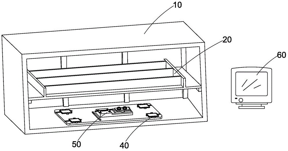
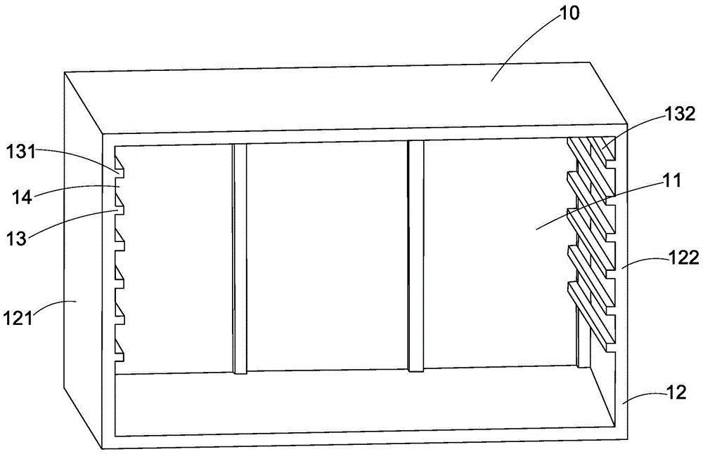
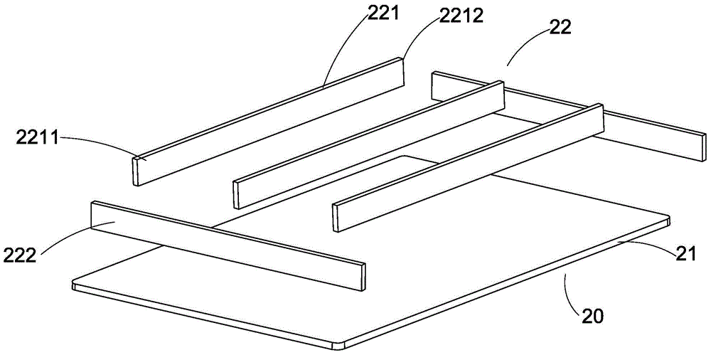
[0076] Such as Figure 1 to Figure 7 Shown is a focusing system based on a multi-camera module in a near-infrared environment according to a preferred embodiment of the present invention, which includes a focusing obscura 10, a standard plate holder 20, a test standard plate 30, an infrared light source 40, a focusing Fixture 50, analysis center 60. The multi-camera module includes multiple cameras, and the focusing system is suitable for performing foc...


PUM


Abstract

The invention relates to a method and a system for focusing a multi-camera module based on a near-infrared environment. The focusing method comprises the steps that infrared light arrives at a test standard plate and gets into each camera of the multi-camera module after being reflected; a focusing operation is carried out on the cameras through a focusing hand wheel; image information acquired by each camera is sent to an analysis center to process, and whether a next step of the focusing operation is carried out continuously or not is judged according to a processing result or the multi-camera module is judged to be unqualified. The method provided by the invention not only can greatly reduce the manufacturing cost of test equipment and simplify the focusing mode, but also reduces the damage probability of a test line by being matched with a special focusing tool. Meanwhile, the production probability is improved, and the matching difference between two lenses can be eliminated by being matched with software.

Description

technical field [0001] The present invention relates to a camera module focusing method and system thereof, in particular to a multi-camera module focusing method and system based on an infrared environment. Background technique [0002] The camera module is installed on mobile phones, computers, televisions, monitoring equipment or other digital devices for image information collection. Camera modules are generally composed of lenses, lens barrels, lens holders, photosensitive chips, resistors, capacitors, and circuit boards. The lens is installed in the lens barrel, and the lens barrel is screwed together with the lens holder through threads, and the focal length of the camera is adjusted by screwing the lens barrel up and down. Before the camera module leaves the factory, it needs to be focused. When focusing, the usual method is to use light to make the photosensitive chip obtain image data and then transmit it to the computer according to the principle of chip imaging...

Claims


Application Information

Patent Timeline
Patent Type & Authority Applications(China)
IPC IPC(8): G03B43/00G03B13/32
Inventor 顾亦武柳高烽邹亿均王舒磊
Owner NINGBO SUNNY OPOTECH CO LTD
Learn More