Eureka AIR delivers breakthrough ideas for toughest innovation challenges, trusted by R&D personnel around the world.

A device and method for measuring surfactant concentration distribution of CO2 emulsion during percolation

A technology of surfactant and determination method, applied in the direction of measuring device, analytical material, instrument, etc., can solve the problem of no measurement and no given surfactant concentration distribution, etc., and achieve the effect of high accuracy and simple operation.

Active Publication Date: 2016-08-24
CHINA UNIV OF PETROLEUM (EAST CHINA)
View PDF7 Cites 2 Cited by
  • Summary
  • Abstract
  • Description
  • Claims
  • Application Information

AI Technical Summary

Problems solved by technology

The patent application number CN201110191927.4 discloses a preparation method and concentration measurement of a low-concentration viscoelastic surfactant solution, but does not give the concentration distribution of the surfactant in the seepage process
[0004] Related studies only measured the distribution coefficient and concentration distribution of compounds in water or oil, but did not involve the core seepage process and CO 2 Soluble surfactants in CO 2 / method of concentration distribution in water systems, without the determination of CO during seepage 2 Soluble surfactants in CO 2 Method and device for concentration distribution in water system

Method used


Image

  • A device and method for measuring surfactant concentration distribution of CO2 emulsion during percolation
  • A device and method for measuring surfactant concentration distribution of CO2 emulsion during percolation

Examples


Embodiment 1

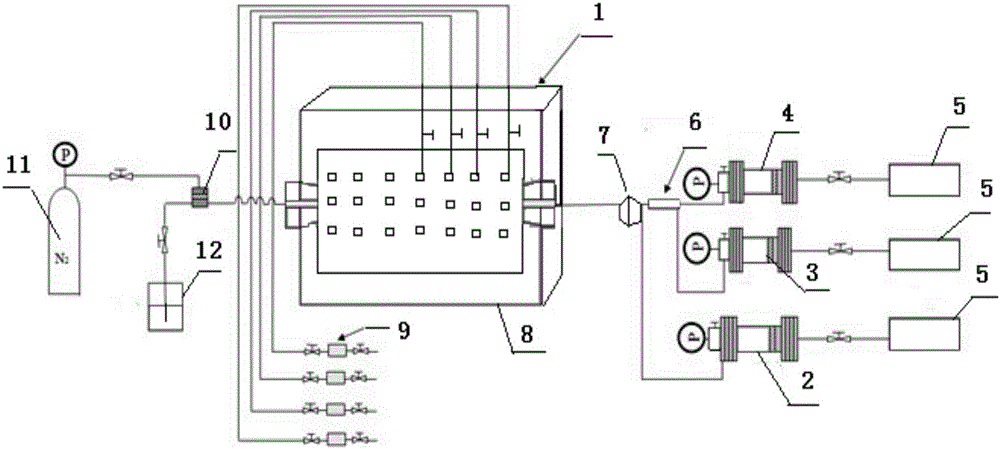
[0029] Such as figure 1 , 2 As shown, a measurement of CO 2 The device for the concentration distribution of the surfactant during the seepage of the emulsion includes a square sand-filled core model 1 filled with quartz sand; the sand core model includes a square metal shell 9-4, and a square inner shell 9-4 is arranged inside the shell 9-4. cavity, the inner cavity is filled with quartz sand with a particle size between 120 and 140 mesh, the inlet and outlet ends of the shell 9-4 are respectively provided with threaded joints, and there are 21 sampling ports on the top surface of the sand-filled core model 1 8. The sand-filled core model 1 is surrounded by a heating insulation cover, which is convenient for heating and insulation.

[0030] The inlet end of the sand-packed core model 1 is connected with a phase-parallel emulsion generator and a crude oil piston 9-5 type intermediate container 2 through a six-way valve 7, and the inlet end of the emulsion generator is conne...

Embodiment 2

[0034] Adopt embodiment 1 to measure CO 2 The assay method that the device that the surfactant concentration distribution of emulsion carries out during percolation process comprises the following steps:

[0035]Step 1: Heat the core temperature of the sand-filled core model 1 to 30°C to 90°C, and maintain the temperature for 12 hours, and then apply confining pressure to the core through the gas source bottle 11; set the back pressure to 10MPa, and the pressure is The outlet pressure of the sand pack model determines the reservoir conditions where the sand pack model is located.

[0036] Step 2, vacuumize the core of sand-filled core model 1 and saturate it with water, then pump crude oil into the core until the core is displaced by crude oil to the state of irreducible water;

[0037] Step 3, using advection pump 5 to separate the CO 2 CO in intermediate container 4 of gas piston 9-5 type 2 Gas and surfactant piston 9-5 The surfactant solution in the intermediate containe...


PUM

PropertyMeasurementUnit
particle size (mesh)aaaaaaaaaa

Abstract

The invention relates to a device and a method for measuring surfactant concentration distribution in a CO2 emulsion percolation process. The device comprises a sand-filling core model, wherein the inlet end of the sand-filling core model is connected with emulsion generators and crude oil piston type intermediate containers which are connected in parallel; the inlet ends of the emulsion generators are connected with CO2 piston type intermediate containers and surfactant piston type intermediate containers which are connected in parallel; the outlet end of the sand-filling core model is connected with a gas source bottle and a liquid containing bottle which are connected in parallel through back-pressure valves; a plurality of equal-interval sampling openings are formed in the top surface of the sand-filling core model and are communicated with the core in the sand-filling core model; each sampling opening is connected with a sampler through a pipeline with a valve. When sampling is carried out at different parts of the model, water phases are separated from CO2 phases, CO2 phase samples are dissolved in water, and the high performance liquid chromatography (HPLC) is adopted to detect the concentration of the surfactant. The device and the method are simple in operation, and the detected accuracy is high.

Description

technical field [0001] The invention relates to a method for measuring CO 2 Device and method for surfactant concentration distribution during emulsion seepage. Background technique [0002] Due to CO 2 It is a gas with high solubility in both oil and water. When it dissolves in a large amount in crude oil, it can expand the volume of crude oil, decrease its viscosity, and reduce the interfacial tension between oil and water. Compared with other oil displacement technologies, carbon dioxide flooding has the advantages of wide application range, low cost of oil displacement, and significant improvement of oil recovery. This technology can not only meet the needs of oil field development, but also solve the problem of carbon dioxide sequestration and protect the atmospheric environment. Under reservoir conditions, CO 2 Generally in a supercritical state (temperature and pressure are above 31.1°C and 7.38MPa respectively), CO 2 The fluid has high mobility and strong fluidi...

Claims


Application Information

Patent Timeline
Patent Type & Authority Patents(China)
IPC IPC(8): G01N33/00
Inventor 李松岩李兆敏刘己全李宾飞张超王飞
Owner CHINA UNIV OF PETROLEUM (EAST CHINA)
Why Eureka
Eureka Blog
Learn More