A supersonic combustion chamber flame stabilization device

A flame stabilization and combustion chamber technology, applied in combustion methods, combustion equipment, fuel supply, etc., can solve problems affecting flame stability, total pressure loss, etc., and achieve the effect of ensuring flame stability, small pressure loss, and enhanced mixing

Active Publication Date: 2017-05-03
NAT UNIV OF DEFENSE TECH
View PDF10 Cites 0 Cited by
  • Summary
  • Abstract
  • Description
  • Claims
  • Application Information

AI Technical Summary

Problems solved by technology

Although this existing structure can improve the mixing of fuel and oxidant to a certain extent, when this structure is adopted, the flow direction vortex and shock wave generated by the trailing edge of the support plate 01 will bring obvious total pressure loss, so huge Affects the stability of the flame

Method used


Image

  • A supersonic combustion chamber flame stabilization device
  • A supersonic combustion chamber flame stabilization device
  • A supersonic combustion chamber flame stabilization device

Examples


Embodiment 1

[0031] as attached figure 2 to the attached Figure 7 shown, with figure 2 to the attached Figure 7 A specific embodiment of a supersonic combustion chamber flame stabilization device is provided.

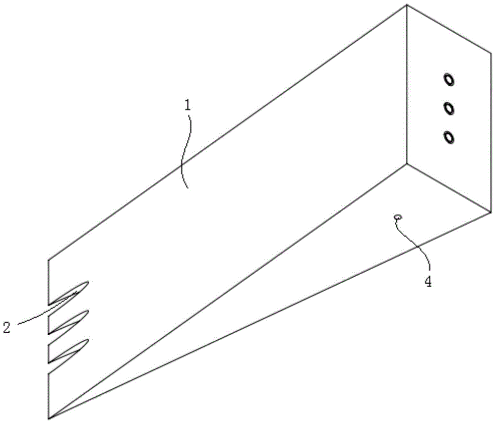
[0032] The flame stabilizing device of the supersonic combustion chamber includes: a support plate 1 installed and fixed inside the supersonic combustion chamber.

[0033] The oxidant through-holes 2 are arranged inside the support plate 1 for the transmission of the oxidant. The number of the oxidant through-holes 2 can be specifically selected according to the needs. In this embodiment, three parallel oxidant through-holes 2 are provided. One end of the oxidant through hole 2 is an air inlet for the input of oxidant; It is arranged on the rear edge of the support plate 1.

[0034] The spiral guide groove 3 is arranged on the inner wall of the oxidant through hole 2, and is used to drive the oxidant to spirally rotate in the oxidant through hole 2. Specifically, when the s...

Embodiment 2

[0043] The present invention also provides a specific embodiment when the supersonic combustion chamber flame stabilization device is in use, wherein, Figure 8 It is a schematic diagram of the structure of the device of the present invention installed in the flow channel.

[0044] as attached Figure 8As shown, the height of the flow channel provided by this embodiment is 50 mm, the upper and lower parts of the front section of the flow channel are parallel, and the upper surface of the flow channel at a distance of 23 mm from the front edge of the support plate expands outward by 3°, and the support plate 1 is set at the middle position in the height direction of the flow channel. The support plate 1 used in this embodiment is a wedge-shaped support plate, the total length of which is 32 mm, the distance from the front edge of the wedge-shaped support plate to the fuel conduit 4 is 23 mm, and the angle between the upper surface and the lower surface of the wedge-shaped suppo...


PUM


Abstract

The invention discloses a flame stabilization device of a supersonic speed combustion chamber. The flame stabilization device comprises a supporting plate, oxidizing agent through holes, spiral guiding grooves and fuel guiding tubes. The supporting plate is fixedly installed inside the supersonic speed combustion chamber, the oxidizing agent through holes are formed inside the supporting plate and used for conveying oxidizing agents, the spiral guiding grooves are formed in the inner walls of the oxidizing agent through holes and used for driving the oxidizing agents to spirally rotate inside the oxidizing agent through holes, and the fuel guiding tubes are arranged inside the oxidizing agent through holes and used for conveying fuel. Through forming the oxidizing agent through holes with the spiral guiding grooves inside the supporting plate, the oxidizing agents will be output clockwise and anticlockwise in a spiral rotation mode when passing through the oxidizing agent through holes; meanwhile, because the fuel guiding tubes are arranged inside the oxidizing agent through holes, the fuel will be driven by the oxidizing agents to rotate when output at an outlet, then mixing of the fuel and the oxidizing agents is effectively improved, and the combustion efficiency of the fuel is improved; in addition, by the adoption of the structure, the pressure loss at the mixing position of the fuel and the oxidizing agents is small, and flame stability can be effectively guaranteed.

Description

technical field [0001] The present invention relates to a supersonic combustion chamber, and more specifically relates to a flame stabilizing device for a supersonic combustion chamber. Background technique [0002] The premise of fuel combustion is that the fuel and oxidant are mixed at the molecular weight level, and in some high-speed combustion devices, such as supersonic combustion chambers, the airflow velocity is very fast, and the residence time of the airflow in the combustion chamber is very short, so the fuel and oxidant often Adequate mixing is difficult to occur, which greatly affects the efficiency of fuel combustion. [0003] In order to improve the combustion efficiency of fuel, scholars from various countries have done a lot of research on the mixing of fuel and oxidant in supersonic combustors. Studies have shown that there are a large number of large-scale vortices in the fuel-oxidant mixing layer of the supersonic combustor, and when these vortices are a...

Claims


Application Information

Patent Timeline
Patent Type & Authority Patents(China)
IPC IPC(8): F23K1/00F23K3/00
Inventor 赵国焱孙明波蔡尊
Owner NAT UNIV OF DEFENSE TECH
Why Eureka
Try Eureka