Installation structure of rear vibration isolation type electric vehicle battery pack

A technology for electric vehicles and installation structures, applied in the direction of electric power devices, transportation and packaging, power devices, etc., can solve the problems of vibration isolation effect of battery pack forward turning, achieve good shock isolation and energy absorption effect, and reasonable use of space

Active Publication Date: 2017-09-29
YANCHENG INST OF TECH
View PDF7 Cites 0 Cited by
  • Summary
  • Abstract
  • Description
  • Claims
  • Application Information

AI Technical Summary

Problems solved by technology

[0004] The present invention provides a battery pack installation structure of a rear mounted vibration isolation type electric vehicle that can prevent the battery pack from turning forward during a collision and has a good vibration isolation effect, and solves the problems existing in the existing rear installed automobile battery pack installation structure. During a collision, the battery pack is prone to flipping forward and the vibration isolation effect is poor

Method used


Image

  • Installation structure of rear vibration isolation type electric vehicle battery pack
  • Installation structure of rear vibration isolation type electric vehicle battery pack
  • Installation structure of rear vibration isolation type electric vehicle battery pack

Examples


Embodiment 1

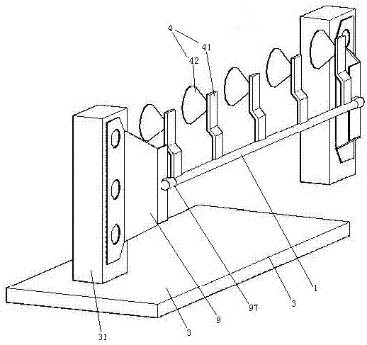
[0027] Embodiment one, see figure 1 , a rear vibration isolation battery pack installation structure for an electric vehicle, comprising a vehicle floor 3 and a front bumper 1 .

[0028] The car floor 3 is positioned between the front of the trunk behind the car and the rear of the rear seat during use. Both sides of the automobile floor 3 are provided with a connecting column 31 .

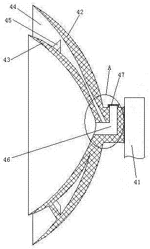
[0029] The front bumper 1 is a tubular structure, specifically a stainless steel tube. The front bumper 1 extends in the width direction of the vehicle. Front bumper 1 is positioned at the rear of the rear row seat of automobile. The front bumper 1 is connected with five battery pack fixing mechanisms 4 . The five battery pack fixing mechanisms 4 are distributed along the length direction of the front bumper 1 , that is, the width direction of the vehicle. The battery pack fixing mechanism 4 includes a connection base 41 and a first suction cup 42 connected to the rear side of the connection b...

Embodiment 2

[0035] Embodiment two, the difference with embodiment one is:

[0036] see Image 6 , the connecting frame 9 is connected with a heat preservation mechanism 8 . The connecting frame 9 also includes a connecting rod 91 and five damping rods 92 . The connecting rod 91 is an arc-shaped structure that arches upwards (of course, downwards is also possible). The five damping rods 92 are a longitudinal damping rod 921 , two horizontal damping rods 922 and two vertical damping rods 923 . One end of the connecting rod 91 is connected with the connecting post 31 . The other end of the connecting rod 91 is connected with one end of the longitudinal damping rod 921 . One end of the two transverse damping rods 922 and the other end of the longitudinal damping rod 921 are connected together. The upper ends of the two vertical damping rods 923 are respectively connected with the other ends of the two transverse damping rods 922 . The lower ends of the two vertical damping rods 923 are ...


PUM


Abstract

The invention relates to the technical field of manufacturing of new energy automobiles. A rear vibration isolation electric vehicle battery pack installation structure comprises a front stop lever and an automobile floor positioned between a trunk and back seats, wherein the front stop lever is of a tubular structure; the front stop lever extends along the width direction of an automobile; the front stop lever is provided with a plurality of battery pack fixing mechanisms along the length direction of the front stop lever; each battery pack fixing mechanism comprises a connection seat connected together with the front stop lever, a first suction cup connected to the back side of the connection seat and a second suction cup positioned in the first suction cup; the first suction cups and the second suction cups define adsorption tanks; two ends of the front stop lever are connected with connection frames which are connected together with the automobile floor. The rear vibration isolation electric vehicle battery pack installation structure has the advantages of capability of preventing a battery pack from being overturned and good vibration isolation effect, and the problems that the battery pack is easily overturned in bumps of the existing battery pack installation structure installed at the rear and the vibration isolation effect is poor are solved.

Description

technical field [0001] The invention relates to the technical field of new energy automobile manufacturing, in particular to a rear vibration-isolation electric automobile battery pack installation structure. Background technique [0002] An electric vehicle is provided with a battery pack for driving a motor, and the battery pack is installed in the vehicle body through a battery pack installation structure. The installation structure of the battery pack is divided into two ways: front and rear according to the position installed on the vehicle body. In the patent document with the Chinese patent number 201220611004X, the authorized publication date being May 29, 2013, and the patent document titled "An Integrated Battery Pack Installation Structure", a front-mounted battery pack installation structure is disclosed, namely The battery pack is installed in the cabin of the car. In the Chinese patent application number 201310221136, the publication date is December 25, 2013...

Claims


Application Information

Patent Timeline
Patent Type & Authority Patents(China)
IPC IPC(8): B60K1/04
Inventor 刘富豪夏基胜
Owner YANCHENG INST OF TECH
Why Eureka
Try Eureka