
Production apparatus and manufacturing method of fiber-reinforced ring

A technology of fiber reinforcement and production equipment, which is applied in the field of fiber reinforcement rings for cryogenic containers and its manufacturing, can solve the problems of high price of winding machines, achieve the effects of improving bridges and cavities, improving performance, and reducing precision requirements

Active Publication Date: 2015-07-22
SHENZHEN UNITED IMAGING HEALTHCARE CO LTD
View PDF5 Cites 4 Cited by
  • Summary
  • Abstract
  • Description
  • Claims
  • Application Information

AI Technical Summary

Problems solved by technology

However, this method requires the winding machine to be linked in two axes. For products with narrow thickness, especially high precision axial feed accuracy is required; so the price of the winding machine is relatively high.

Method used

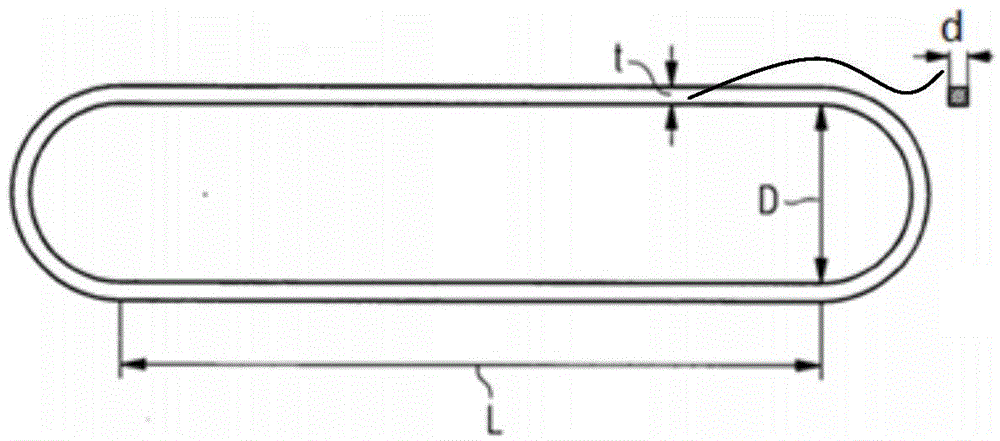
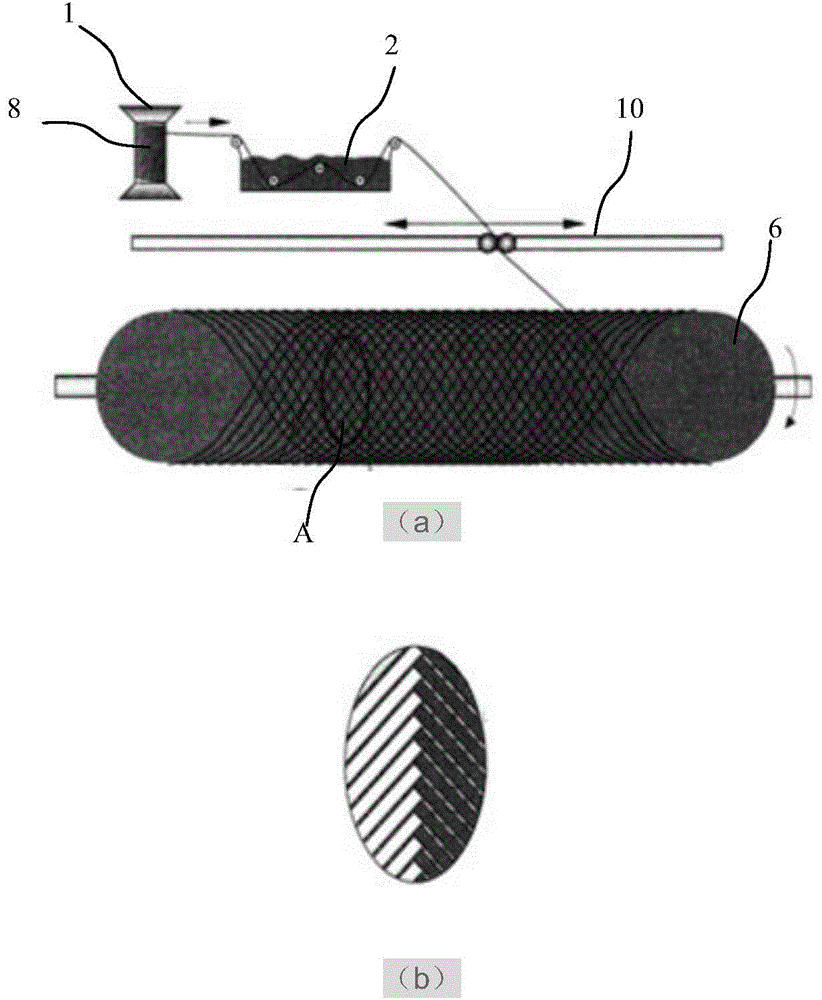
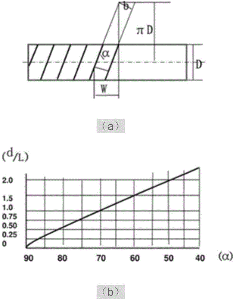

Image

  • Production apparatus and manufacturing method of fiber-reinforced ring
  • Production apparatus and manufacturing method of fiber-reinforced ring
  • Production apparatus and manufacturing method of fiber-reinforced ring

Examples


Embodiment 1

[0048] Figure 7 It is a structural schematic diagram of a production device for a fiber reinforced ring in an embodiment of the present invention.

[0049] See Figure 7 , the production device of the fiber-reinforced ring provided by the present invention includes: a yarn twisting shaft 1, a dipping pool 2, a wire winding mouth 3, a tensioning device 4, a flattening device 5, a mandrel 6 and a driving System 7, the mandrel 6 is connected to the driving system 7 through the first transmission belt 71, the yarn twisting shaft 1, the winding nozzle 3, the tensioning device 4 and the flattening device 5 are arranged in sequence for the roving twist 8 to pass through to become a flat yarn twist 9.

[0050] Figure 8 It is a structural schematic diagram of the round inlet of the winding nozzle in the production device of the fiber reinforced ring in the embodiment of the present invention; Figure 9 It is a schematic cross-sectional view of a rectangular inlet winding nozzle i...

Embodiment 2

[0060] The difference from Embodiment 1 is that this embodiment is dry winding, that is, the early winding process does not impregnate the resin, and after the winding is completed, the resin is injected into the core mold 6 by vacuum filling, and then dried and formed. That is, there is no dipping tank 2 in the production device of the fiber reinforced ring provided in this embodiment, and the roving twist 8 is pulled out from the yarn twist shaft 1 and directly passes through the through hole 31 of the winding nozzle 3 to become a flat yarn twist 9; After the flat yarn twist 9 is wound, the resin is injected into the mandrel 6 by means of vacuum filling, which is formed naturally or dried, and the fiber-reinforced ring is formed after demoulding.

[0061] Compared with the existing technology, Figure 4 In the existing yarn-twist layered structure shown in , the inside of the yarn-twist may be impregnated with resin glue, Figure 12 In the fiber yarn tape layered structure ...


PUM

PropertyMeasurementUnit
sizeaaaaaaaaaa

Abstract

The present invention discloses a production apparatus and a manufacturing method of a fiber-reinforced ring. The production apparatus comprises a yarn twisting shaft for winding of roved twists, a core mold and a drive system, wherein the drive system drives the core mold to rotate. The production apparatus further comprises a yarn winding mouth and a flattening device, wherein the yarn twisting shaft, the yarn winding mouth and the flattening device are sequentially aligned, a through hole for penetrating-through of the yarn twist is formed in the yarn winding mouth, and the outlet end of the through hole presents the flat cross-sectional shape. According to the production apparatus and the manufacturing method of the present invention, only the single-direction winding is adopted to wind the fiber-reinforced ring, such that the space linkage limitation of the existing winding machine is overcome, the problems of bridging, cavity and the like during the winding process are improved, the performance of the fiber-reinforced ring is increased, and the difficulty and the complexity of the production process are reduced.

Description

technical field [0001] The invention relates to a production device of a fiber-reinforced ring and a manufacturing method thereof, in particular to a fiber-reinforced ring for cryogenic containers and a manufacturing method thereof. Background technique [0002] Cryogenic liquefied gases have been widely used in industry, but most of them are very expensive, such as liquid helium used for refrigeration in superconducting magnets. In order to reduce the evaporation of low-temperature medium, the "du Watts" to contain cryogenic liquids. In multi-layer insulated containers, the inner container and shield at low temperature are connected to the outer container by tabs (or rods). Due to the large load suspended by the pull ring (or pull rod), it is required to have better mechanical properties. In addition, the heat conduction from the outside of the tie rod to the inner container is: [0003] Q = A L ∫ ...

Claims


Application Information

Patent Timeline
Patent Type & Authority Applications(China)
IPC IPC(8): B29C70/34B29C33/76
Inventor 张强
Owner SHENZHEN UNITED IMAGING HEALTHCARE CO LTD
Learn More