Clamping unit of a molding machine and method for monitoring the clamping unit of a molding machine

A molding machine and molding mold technology, which is applied in the field of monitoring the clamping unit of the molding machine, can solve the problems of cumbersome structure and the inability to compensate the deviation of the lower mold, etc.

Active Publication Date: 2017-08-18
ENGEL AUSTRIA
View PDF1 Cites 0 Cited by
  • Summary
  • Abstract
  • Description
  • Claims
  • Application Information

AI Technical Summary

Problems solved by technology

[0008] The disadvantage here is that the upper tool has to be moved in a plane perpendicular to the closing direction of the forming tool, which is structurally rather cumbersome
[0009] A further disadvantage is that deviations with respect to the lower tool cannot be compensated

Method used


Image

  • Clamping unit of a molding machine and method for monitoring the clamping unit of a molding machine
  • Clamping unit of a molding machine and method for monitoring the clamping unit of a molding machine
  • Clamping unit of a molding machine and method for monitoring the clamping unit of a molding machine

Examples


Embodiment Construction

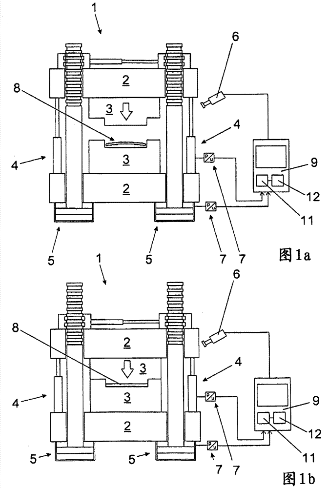
[0037]The clamping unit 1 is shown in FIGS. 1 a and 1 b. The mold clamping unit comprises two clamping plates 2 on which the components of the forming mold 3 are installed respectively. In addition, two fast-stroke drives 4 and four power-stroke drives 5 are respectively provided, which allow high pressing forces to be applied to the mold 3 . (Due to the manner of presentation, only two of the four power stroke drives 5 are visible.) The exact design of the clamping unit 1 is not important for the invention. The hydraulic clamping unit 1 shown here is therefore only exemplary with four longitudinal beams. Likewise, clamping units with frames can be used, for example, with electronic crank lever machines or other hybrids. Furthermore, it is not important for the invention whether a horizontal or vertical clamping unit is used.

[0038] FIG. 1 a shows the clamping unit 1 after the semi-finished product 8 , in this case a fiber fabric, has been placed in the mold 3 . The clam...


PUM


Abstract

The invention relates to a clamping unit of a molding machine comprising two clamping plates, at least one drive, at least one measuring instrument and a control or regulation unit, wherein at least one reference clamp can be stored in a memory of the control or regulation unit Force and / or at least one reference position of at least one clamping plate and / or at least one reference force introduction point and / or reference position of the semi-finished product, and the processor of the control or regulation unit is configured for, if at least one clamping force value and at least one reference clamping force and / or at least one position value and at least one reference position and / or at least one calculated force introduction point and at least one reference force introduction point and / or the measured position of the semi-finished product and If the reference positions do not substantially coincide, the mold clamping movement of the clamping plates and / or the application of the mold clamping force is interrupted or hindered. The invention also relates to a molding machine with a clamping unit and a method for monitoring the clamping unit of a molding machine.

Description

technical field [0001] The invention relates to a clamping unit of a molding machine and to a method for monitoring the clamping unit of a molding machine. Background technique [0002] The method steps that are frequently applied in injection molding machines include placing the semi-finished product in the forming tool, closing the forming tool and introducing and hardening the reactive liquid mixture, after which the forming tool can be opened and the resulting component demoulded. [0003] For example, fiber fabrics or the like can be used as semi-finished products here. [0004] Precise positioning and the properties of the semi-finished product are crucial for the quality of the resulting component. Especially for non-rigid semi-finished products, this precise positioning poses certain challenges for automating the method. This has the result that complex quality controls have to be carried out in the event of incorrect positioning of the semi-finished product, or th...

Claims


Application Information

Patent Timeline
Patent Type & Authority Patents(China)
IPC IPC(8): B29C45/66B29C45/76
CPCB29C45/76B29C45/7653B29C45/80B29C45/14B29C2945/76013B29C2945/76083B29C2945/76227B29C2945/76294B29C2945/76464B29C43/58B29C2043/5808B29C2043/5833B29C2043/5891
Inventor H·施泰因帕泽H·蔡德尔霍费尔P·艾格
Owner ENGEL AUSTRIA
Why Eureka
Try Eureka