
Clutch unit and outer friction plate support

A technology of clutch device and plate support, which is applied in clutches, friction clutches, fluid-driven clutches, etc., and can solve problems affecting the function of clutch devices, etc.

Inactive Publication Date: 2017-11-28
SCHAEFFLER TECH AG & CO KG
View PDF5 Cites 0 Cited by
  • Summary
  • Abstract
  • Description
  • Claims
  • Application Information

AI Technical Summary

Problems solved by technology

Thus affecting the function of the individual components of the clutch unit

Method used


Image

  • Clutch unit and outer friction plate support
  • Clutch unit and outer friction plate support
  • Clutch unit and outer friction plate support

Examples


Embodiment Construction

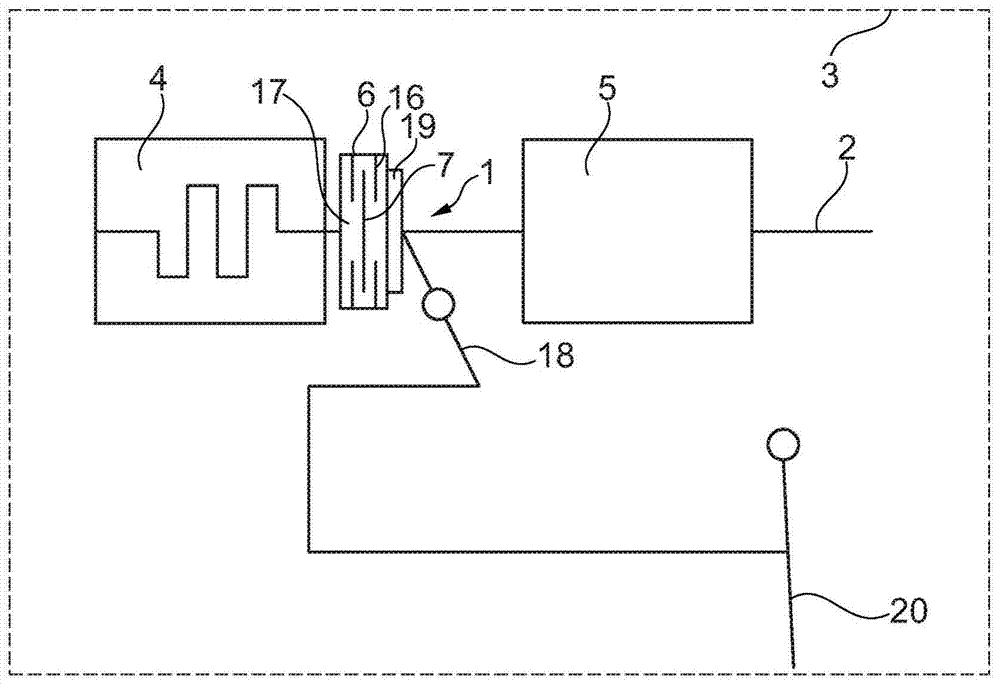
[0035] figure 1 Motor vehicle 3 with clutch device 1 is shown schematically. The clutch device 1 serves to transmit torque between the drive unit 4 and the transmission 5 . The clutch device 1 has an outer friction plate support 6 and an inner friction plate support 7, the outer friction plate support 6 has an outer friction plate 16, the inner friction plate support 7 has an inner friction plate 17, the outer friction plate support 6 and the inner friction plate support 7 can be frictionally connected to each other or disconnected from each other via disk spring 19 and release device 18 . The release device 18 is actuated via a clutch pedal 20 . The torque is transmitted from the drive unit 4 via the clutch device 1 to the transmission 5 and from the transmission 5 to the drive train 2 .

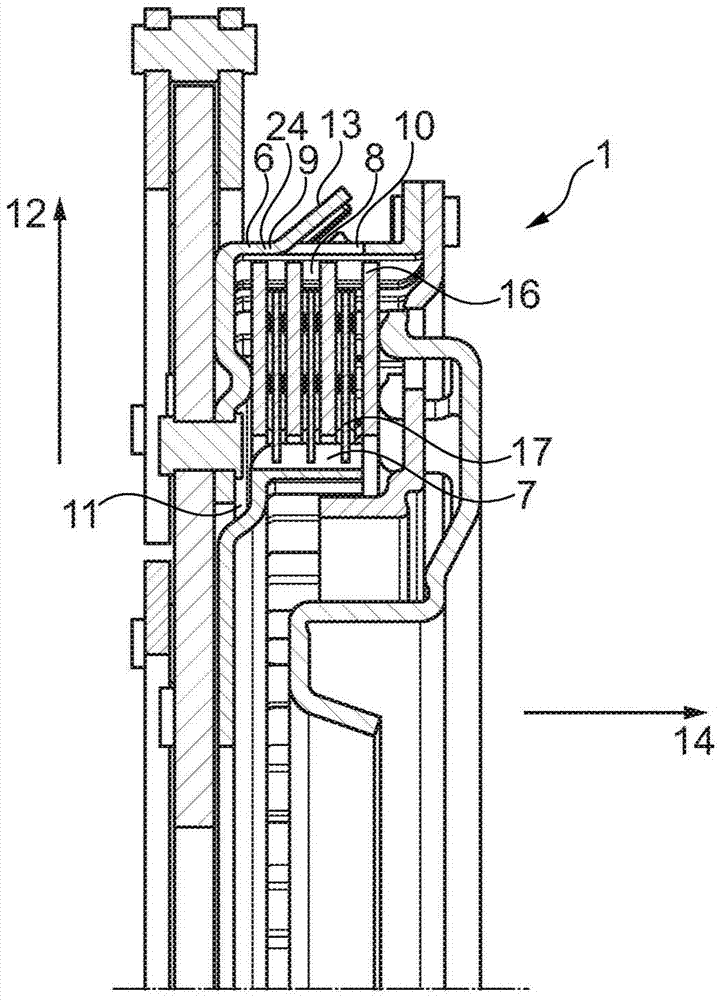
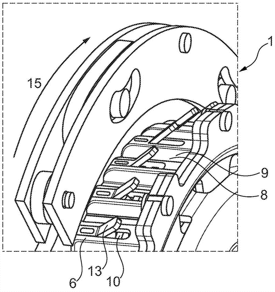
[0036] figure 2A side view of the clutch device 1 is shown in section. The clutch device 1 has an outer disk carrier 6 and an inner disk carrier 7 . The outer disk carrier 6 is posit...


PUM


Abstract

The invention relates to a coupling device, particularly for arranging in a drive train of a motor vehicle between a drive unit and a gearbox for transmitting torques. Said coupling device comprises at least one outer plate carrier and one inner plate carrier, said outer plate carrier comprising at least one opening, on a peripheral surface that has a toothing, for the purpose of conducting a hydraulic liquid in a radial direction. At least one guide element is provided which is suitable for deflecting, in an axial direction, the hydraulic liquid which flows in the radial direction outwards through the at least one opening. The invention also relates to an outer plate carrier. The coupling device shown here allows a hydraulic liquid to be conveyed towards specific components of the coupling device in a targeted manner.

Description

technical field [0001] The invention relates to a (wet-running) clutch arrangement and an outer disk carrier, in particular for being arranged in a drive train of a motor vehicle between a drive unit and a transmission for torque transmission. Background technique [0002] In particular, the clutch arrangement can be used as a double clutch. The invention is directed in particular to so-called wet-running friction clutches, for example in the form of multi-plate clutches, which operate under the action of a viscous operating medium, such as a hydraulic fluid (eg oil). The friction disks of the clutch arrangement are cooled by hydraulic fluid. In addition to the friction disks, further components are arranged in this clutch device, in particular a spring damper unit, which likewise has operating characteristics related to a moderate supply of hydraulic fluid. During the operation of such wet-running clutch devices, it often happens that the supply of hydraulic fluid to indi...

Claims


Application Information

Patent Timeline
Patent Type & Authority Patents(China)
IPC IPC(8): F16D25/12F16D13/68
CPCF16D13/683F16D13/72F16D25/123
Inventor P·瓦尔D·施纳德尔巴赫S·迈恩沙因T·克劳泽
Owner SCHAEFFLER TECH AG & CO KG
Learn More