Assembly jig and assembly method for motor transmission ring

A technology for assembling fixtures and transmission rings, which is applied in the direction of manufacturing tools, metal processing, metal processing equipment, etc., can solve the problems of transmission ring life impact, transmission ring damage, etc., and achieve the effect of simple and scientific structural design and convenient assembly and installation

Active Publication Date: 2017-04-05
广东磁瑞磁悬浮科技有限公司
View PDF6 Cites 0 Cited by
  • Summary
  • Abstract
  • Description
  • Claims
  • Application Information

AI Technical Summary

Problems solved by technology

This method can only be carried out at room temperature. The deformation of the transmission ring depends on the degree of manual tightening of the screw. In order to ensure smooth assembly, the deformation of the ring in most cases exceeds the actual demand. This forced deformation operation is harmful to the transmission ring. Will cause a certain degree of damage, or have a negative impact on the life of the drive ring

Method used


Image

  • Assembly jig and assembly method for motor transmission ring
  • Assembly jig and assembly method for motor transmission ring
  • Assembly jig and assembly method for motor transmission ring

Examples


Embodiment Construction

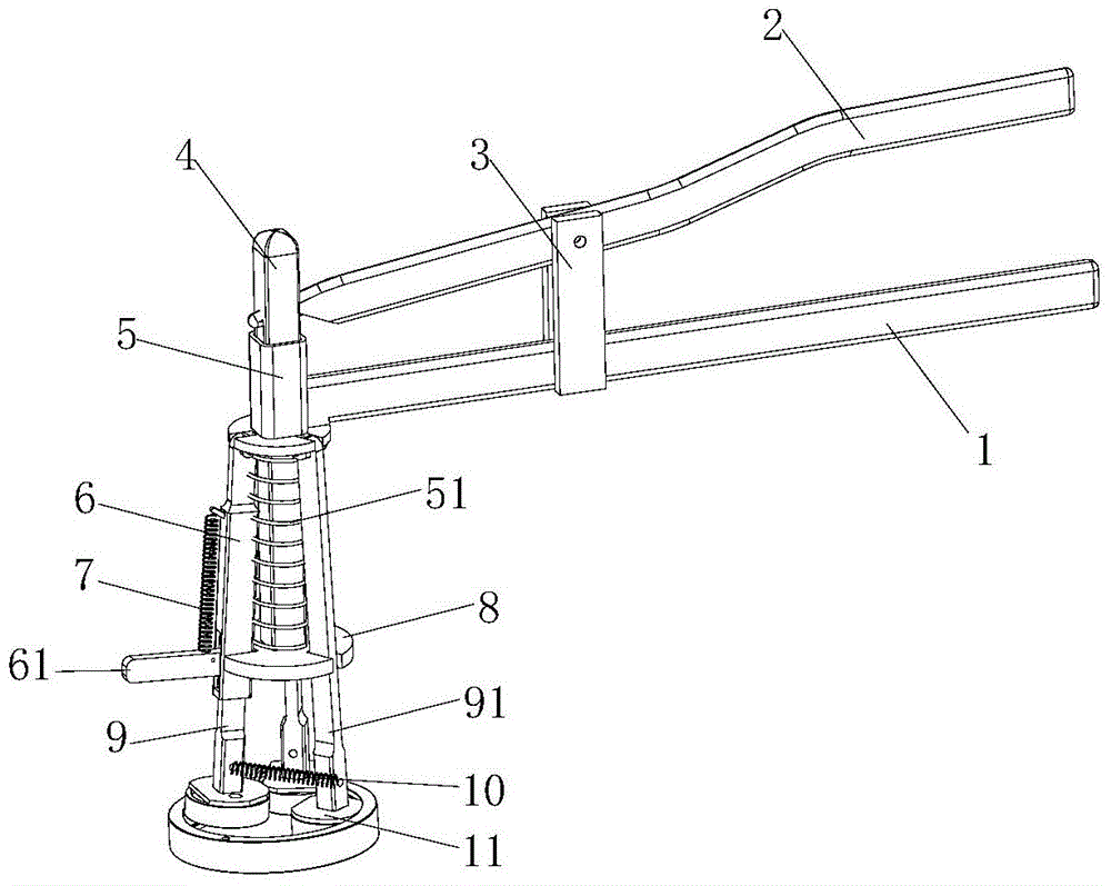
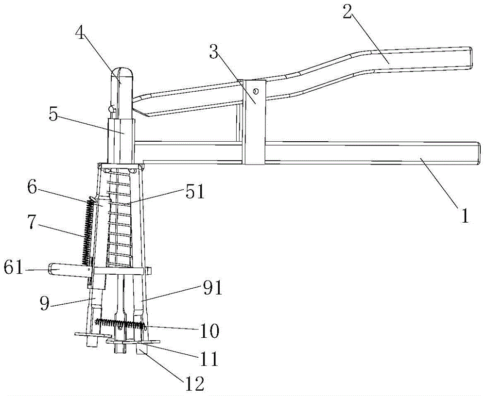
[0023] See Figure 1 to Figure 6 As shown: the present invention includes a fixed handle 1, a movable handle 2, a center rod 4, a fixed rod sleeve 5, a pressure rod sleeve 6, a support plate 8, and a pressure rod 9, and the fixed handle 1 and the movable handle 2 are hinged through a support rod 3 , one end of the movable handle 2 is movably connected to the central rod 4, and the central rod 4 is movably plugged into the fixed rod sleeve 5, and the fixed rod sleeve 5 is connected to one end of the fixed handle 1, and the movable hinge on the fixed rod sleeve 5 is provided with Depression bar 9, movable strut 91, is provided with depression bar sleeve 6 on the depression bar 9, and movable strut 91 is two, is provided with movable support plate 8 between movable support bar 91, depression bar 9, and support plate 8 It is connected with the central rod 4, a return spring 51 is provided between the support plate 8 and the central rod 4, a pressure rod handle 61 is provided on th...


PUM


Abstract

The invention relates to the technical field of motor manufacturing, in particular to a motor transmission ring assembling clamp and method. A fixed handle and a movable handle are hinged through a supporting rod. One end of the movable handle is movably connected with a center rod. The center rod is movably inserted in a fixed rod sleeve. The fixed rod sleeve is connected with one end of the fixed handle. A pressing rod and movable supporting rods are movably hinged to the fixed rod sleeve. The pressing rod is provided with a pressing rod sleeve. A movable supporting disc is arranged between the movable supporting rods and the pressing rod. The supporting disc is connected with a center rod. A reset spring is arranged between the supporting disc and the center rod. The pressing rod is provided with a pressing rod handle, a tension spring is arranged between the pressing rod handle and the pressing rod sleeve, trays are arranged at the tail end of the movable supporting rod and the tail end of the pressing rod, and positioning cylinders are arranged in the centers of the trays. The motor transmission assembling clamp is ingenious in structural design and convenient to assemble and install. According to the assembling method, by means of the assembling clamp, related components are fast assembled when a transmission ring is still in a thermal expansion state, and the transmission ring cannot be damaged in the whole process.

Description

technical field [0001] The invention relates to the technical field of motor manufacturing, in particular to an assembly fixture for a motor drive ring and an assembly method thereof. Background technique [0002] The transmission ring is an important part of a DC motor. It tightly wraps the motor shaft and the rollers. The power is transmitted by friction between the three, and the deceleration is completed in the process of power transmission. In order to obtain sufficient frictional force, a large pressing force must be preset for the roller and shaft during assembly, and this pressing force is provided by the transmission ring. During the operation of the motor, the three rollers roll along the inner circumferential surface of the transmission ring, causing the transmission ring to be squeezed and deformed repeatedly. The maximum pressing force allowed by the transmission ring has a direct impact on the maximum output torque of the motor and the life of the motor. [0...

Claims


Application Information

Patent Timeline
Patent Type & Authority Patents(China)
IPC IPC(8): B23P11/02
CPCB23P11/02B23P11/025
Inventor 任兴华
Owner 广东磁瑞磁悬浮科技有限公司
Why Eureka
Try Eureka