
Self-adaptive optical retina imaging device and method

An adaptive optics and imaging device technology, applied in the field of adaptive optics, can solve problems such as low imaging efficiency, lack of pupil and pupil surface monitoring devices, and inability to achieve wavefront aberration separation of confocal scanning optical paths, thereby improving practicability. Effect

Inactive Publication Date: 2015-07-22
INST OF OPTICS & ELECTRONICS - CHINESE ACAD OF SCI
View PDF9 Cites 13 Cited by
  • Summary
  • Abstract
  • Description
  • Claims
  • Application Information

AI Technical Summary

Problems solved by technology

However, this system only uses a single wavefront sensor, which cannot separate the wavefront aberrations of the confocal scanning optical path and the optical coherence tomography optical path, making the aberration correction accuracy low and affecting the imaging resolution; at the same time, the system lacks a pupil and pupil The surface monitoring device makes the system extremely inconvenient to use and the imaging efficiency is low

Method used


Image

  • Self-adaptive optical retina imaging device and method
  • Self-adaptive optical retina imaging device and method
  • Self-adaptive optical retina imaging device and method

Examples


Embodiment Construction

[0029] Hereinafter, embodiments of the present disclosure will be described with reference to the drawings. However, it should be understood that these descriptions are only exemplary and are not intended to limit the scope of the present disclosure. In addition, in the following description, descriptions of well-known structures and technologies are omitted to avoid unnecessarily obscuring the concept of the present disclosure.

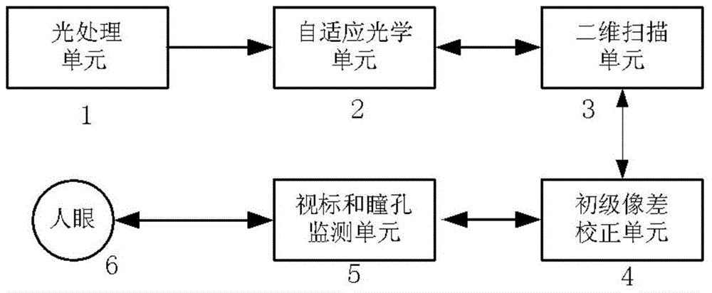
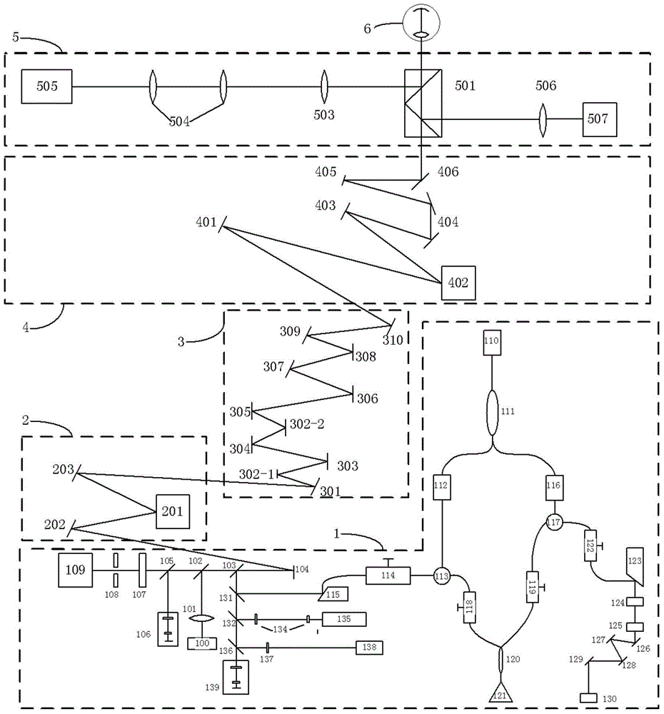
[0030] In order to overcome the above-mentioned shortcomings of the prior art, the present invention provides an adaptive optics retinal high-resolution multi-mode imaging device. By adopting a variety of module combinations, the advantages of adaptive optics technology for high-precision correction of low-order and high-order aberrations of the human eye are fully utilized. At the same time, the co-optic index and multiple monitoring function components are added, which greatly improves the application of the present invention. range. The device can ...


PUM


Abstract

The invention discloses a self-adaptive optical retina imaging device and method. The self-adaptive optical retina imaging device comprises an optical processing unit, a self-adaptive optical unit, a two-dimensional scanning unit and a primary aberration correcting unit. An imaging unit included in the optical processing unit is used for imaging based on signals after high-order aberration compensation and low-order aberration compensation. The self-adaptive optical technology, the confocal scanning imaging technology and the optical coherence tomography are combined, two wavefront sensors are used for detecting wavefront aberration of a confocal scanning light path and an optical coherence tomography light path, meanwhile, two wavefront correctors are used for correcting low-order aberration and high-order aberration of human eyes, low-order aberration and high-order aberration can be conducted on the two light paths, and transverse high resolution imaging and longitudinal high resolution imaging of the human eyes can be achieved at the same time.

Description

Technical field [0001] The present disclosure generally relates to the field of adaptive optics technology, and more specifically, to an adaptive optics retinal imaging device and method capable of realizing high resolution and multiple modes. Background technique [0002] Adaptive optics technology has the ability to measure and correct dynamic wavefront aberrations in real time. When applied to fundus retinal imaging technology, it can correct human eye aberrations that vary randomly in time and space, thereby achieving a human eye close to the diffraction limit. High-resolution imaging of the retina. At present, adaptive optics human eye aberration correction technology has been used in a variety of retinal optical imaging technologies, and it has become an indispensable technical means for high-resolution retinal imaging of the fundus. For example, adaptive optics fundus microscopes, adaptive optics Retina high-resolution imaging systems such as optical confocal scanning oph...

Claims


Application Information

Patent Timeline
Patent Type & Authority Applications(China)
IPC IPC(8): A61B3/14A61B3/12
CPCA61B3/1015A61B3/0091A61B3/102A61B3/1025A61B3/1225G02B21/0012G02B26/101G02B27/0068
Inventor 何益史国华杨金生魏凌李喜琪王志斌张雨东
Owner INST OF OPTICS & ELECTRONICS - CHINESE ACAD OF SCI
Learn More