
Aluminum alloy conductor, alum1inum alloy stranded wire, sheathed wire, wire harness, and method for manufacturing aluminum alloy conductor

A technology for aluminum alloy conductors and manufacturing methods, which is applied in the direction of metal/alloy conductors, cable/conductor manufacturing, and used to reduce the size of conductors/cables, etc., and can solve the problem of limited use positions, low operating efficiency, and inability to withstand impacts, etc. problems, achieve the effect of reducing disconnection and improving work efficiency

Active Publication Date: 2015-07-15
FURUKAWA ELECTRIC CO LTD +1
View PDF7 Cites 21 Cited by
  • Summary
  • Abstract
  • Description
  • Claims
  • Application Information

AI Technical Summary

Benefits of technology

The technical effect of this inventive material described by Aluminum (Al) metal is its ability to resist being bent repeatedly without losing their functioning over time due to factors like temperature changes, moisture exposures, vibrations caused by movement, shocks from outside sources such as people walking around while installing electric cables, motors, door locks, and other items inside vehicles' cabins. This makes them ideal materials for use in batteries, power transmission lines, and electronic devices.

Problems solved by technology

This patented technical issue addressed in this patents relates to improving the mechanical property and flexibility of alkaline metal batteries while maintaining their electricity conduction capabilities without increasing its overall thickness. Additionally, the challenge presented involves achieving higher levels of bend fatigue life under severe conditions involving repetitively bending actions over time.

Method used


Image

  • Aluminum alloy conductor, alum1inum alloy stranded wire, sheathed wire, wire harness, and method for manufacturing aluminum alloy conductor
  • Aluminum alloy conductor, alum1inum alloy stranded wire, sheathed wire, wire harness, and method for manufacturing aluminum alloy conductor
  • Aluminum alloy conductor, alum1inum alloy stranded wire, sheathed wire, wire harness, and method for manufacturing aluminum alloy conductor

Examples


Embodiment 1

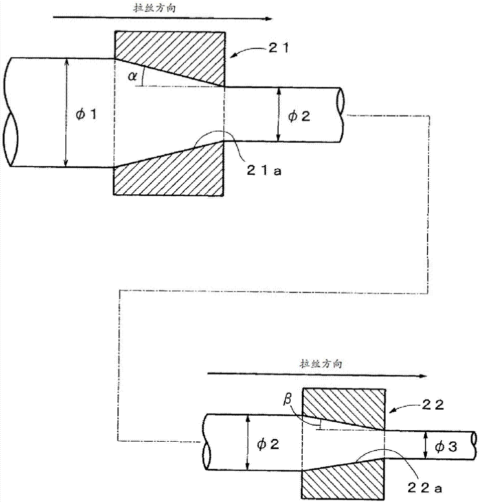
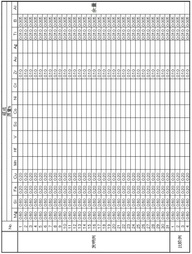
[0104] Mg, Si, Fe, and Al, and optionally added Cu, Zr, Ti, and B were set to the contents (mass %) shown in Table 1, using a Propezer-type continuous casting and rolling machine, while utilizing water-cooled casting The mold continuously casts molten metal and rolls it to make approx. of bars. The casting cooling rate at this time is 1 to 20°C / sec. Next, the first wire drawing was performed so that the processing rates shown in Table 2 were obtained. Then, intermediate heat treatment is performed on the processed material subjected to the first wire drawing, and thereafter, the second wire drawing is performed at the same processing rate as the first wire drawing. the wire diameter. Then, solution heat treatment (first heat treatment) was performed under the conditions shown in Table 2. It should be noted that, in the solution heat treatment, when the batch type heat treatment is used, a thermocouple is wound around the wire rod to measure the temperature of the wire ro...

Embodiment 2

[0106] Mg, Si, Fe, and Al, and optionally added Cu, Mn, Cr, Zr, Au, Ag, Hf, V, Ni, Sc, Co, Ti, and B are the contents shown in Table 3 (mass %) Cooperate, in addition, carry out casting, rolling by the method identical with embodiment 1, make approximately of bars. Next, the first wire drawing was performed so that the processing rates shown in Table 4 were obtained. Then, intermediate heat treatment is performed on the processed material subjected to the first wire drawing, and thereafter, the second wire drawing is performed at the same processing rate as the first wire drawing. the wire diameter. Then, solution heat treatment (first heat treatment) was performed under the conditions shown in Table 4. After the solution heat treatment, aging heat treatment (second heat treatment) was performed under the conditions shown in Table 4 to manufacture aluminum alloy wires.

[0107] Each characteristic was measured by the method shown below about the produced aluminum alloy w...


PUM

PropertyMeasurementUnit
Yield strengthaaaaaaaaaa

Abstract

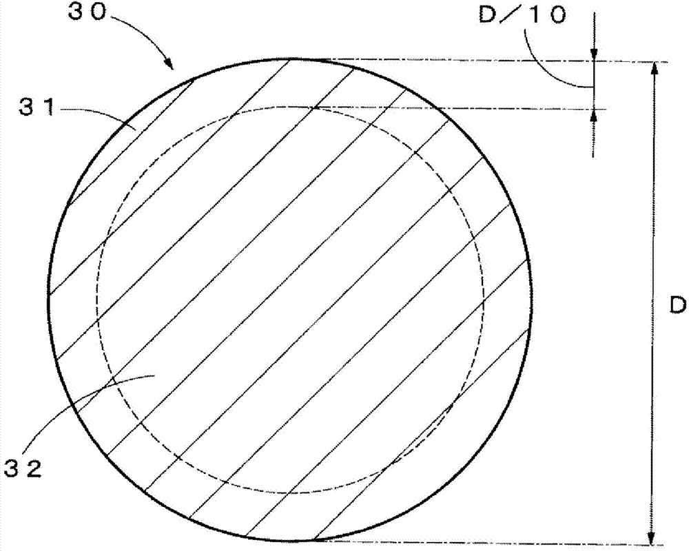
An aluminum alloy conductor having a high conductivity and a high bending fatigue resistance, and further achieving an appropriate proof stress and a high elongation is provided. An aluminum alloy conductor of the present invention has a composition consisting of Mg: 0.10 mass% to 1.00 mass%, Si: 0.10 mass% to 1.00 mass%, Fe: 0.01 mass% to 2.50 mass%, Ti: 0.000 mass% to 0.100 mass%, B: 0.000 mass% to 0.030 mass%, Cu: 0.00 mass% to 1.00 mass%, Ag: 0.00 mass% to 0.50 mass%, Au: 0.00 mass% to 0.50 mass%, Mn: 0.00 mass% to 1.00 mass%, Cr: 0.00 mass% to 1.00 mass%, Zr: 0.00 mass% to 0.50 mass%, Hf: 0.00 mass% to 0.50 mass%, V: 0.00 mass% to 0.50 mass%, Sc: 0.00 mass% to 0.50 mass%, Co: 0.00 mass% to 0.50 mass%, Ni: 0.00 mass% to 0.50 mass%, and the balance: Al and incidental impurities, wherein the aluminum alloy conductor has an average grain size of 1 µm to 35 µm at an outer peripheral portion thereof.

Description


Claims


Application Information

Patent Timeline
Owner FURUKAWA ELECTRIC CO LTD
Learn More