Method for predicting skipping trajectory of hypersonic glide warhead in near space
A hypersonic, near-space technology, applied in special data processing applications, instruments, electrical digital data processing, etc., can solve the problem of low trajectory prediction accuracy of maneuvering targets
- Summary
- Abstract
- Description
- Claims
- Application Information
AI Technical Summary
Problems solved by technology
Method used
Image
Examples
specific Embodiment approach 1
[0046] Specific Embodiment 1: A method for predicting the jumping trajectory of a near-space hypersonic glide warhead according to the present embodiment, which is implemented in the following steps:
[0047] 1. The establishment of the ballistic equation of the hypersonic glide warhead;
[0048]Establish the ballistic equations of hypersonic glide warheads in near space, including aerodynamic calculation equations, acceleration calculation equations, velocity and position calculation equations, velocity and ballistic angle calculation equations, and attitude angle calculation equations;
[0049] Based on the comprehensive calculation equations, the velocity and position equations of the center of mass of the hypersonic glide warhead are obtained as equations (1)-(3).
[0050] 2. Design of tracking filter for hypersonic glide warhead;
[0051] Design the trajectory tracking Kalman filter of the hypersonic glide warhead to track and estimate the position, velocity and accelera...
specific Embodiment approach 2
[0059] Specific implementation mode two: the difference between this implementation mode and specific implementation mode one is:
[0060] Definition of the first step coordinate system
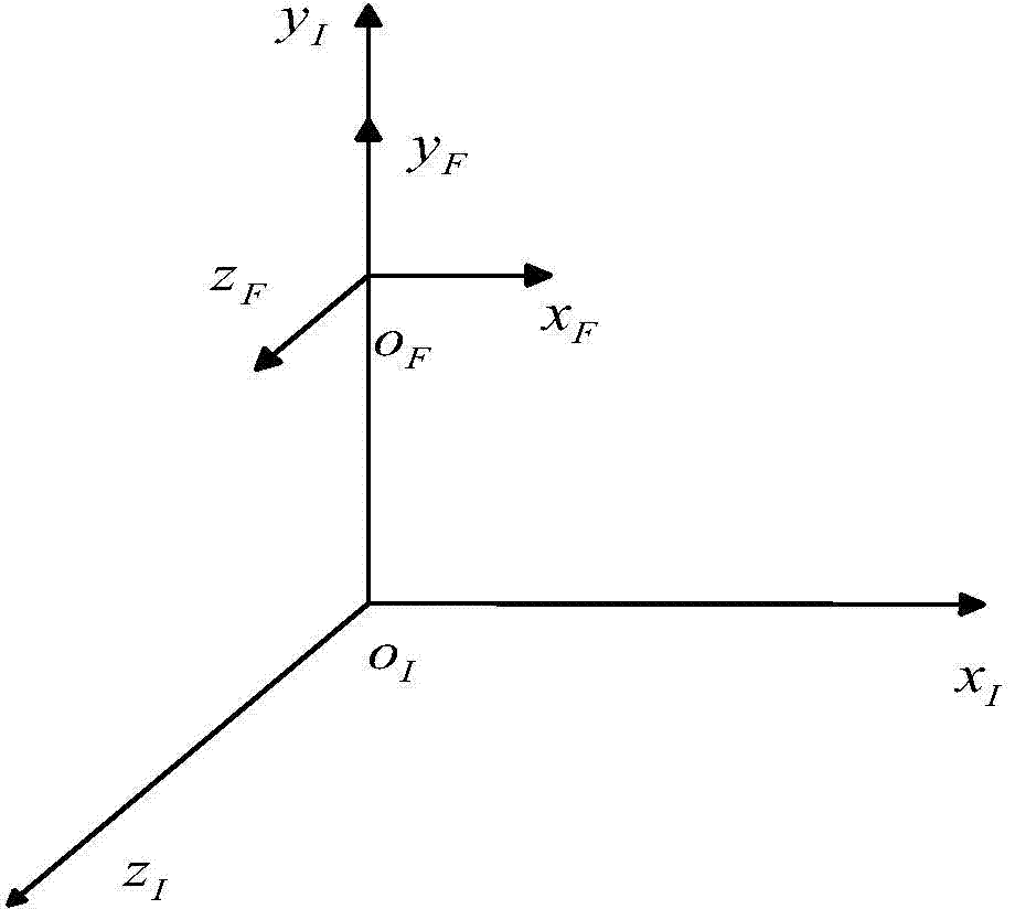
[0061] In order to obtain the prediction method of the hypersonic glide warhead jumping trajectory in the near space, a set of equations need to be established to describe the motion of the hypersonic glide warhead in the near space. To this end, several related coordinate systems need to be defined first.
[0062] (1) Geocentric inertial coordinate system (o I x I the y I z I )
[0063] Such as figure 1 As shown, the origin o I at the center of the earth, o I the y I Pointing to ground radar detection point, o I x I axis lies in the target incoming plane, with o I the y I The axis is vertical, pointing to the target is positive, o I z I Determined by the right-hand rule.
[0064] (2) The inertial coordinate system of the detection point (o F xyz)
[0065] The origin is the ...
specific Embodiment approach 3
[0116] Specific implementation mode three: the difference between this implementation mode and specific implementation mode one or two is that step two is specifically:
[0117] (1) On the three axes of the inertial coordinate system of the detection point, the Singer model is used to describe the variation of the acceleration component of the hypersonic glide warhead, namely
[0118] a · x = - λ x a x + w x a · y = ...
PUM
 Abstract
Description
Claims
Application Information
 - Generate Ideas
- Intellectual Property
- Life Sciences
- Materials
- Tech Scout
- Unparalleled Data Quality
- Higher Quality Content
- 60% Fewer Hallucinations
Browse by: Latest US Patents, China's latest patents, Technical Efficacy Thesaurus, Application Domain, Technology Topic, Popular Technical Reports.
© 2025 PatSnap. All rights reserved.Legal|Privacy policy|Modern Slavery Act Transparency Statement|Sitemap|About US| Contact US: help@patsnap.com


