Current detecting circuit and feedback control circuit applied to laminated control power supply and power supply

A technology of current detection circuit and control power supply, which is applied in the direction of measuring current/voltage, control/regulation system, measuring device, etc. It can solve the problem of idle waste of current detection device, and achieve the effect of simple circuit and reduced use

Active Publication Date: 2015-07-15
SICHUAN INJET ELECTRIC CO LTD
View PDF7 Cites 3 Cited by
  • Summary
  • Abstract
  • Description
  • Claims
  • Application Information

AI Technical Summary

Problems solved by technology

[0005] The purpose of the present invention is to overcome the problem that at any working time in the prior art, only the current detection devices in two tap branches work at most, causing the current detection devices in the remaining tap branches to be idle and wasteful, and to provide a method that greatly reduces the The current detection circuit of the current detection device in the tap branch for the lamination control power supply is used to detect the current when the lamination control power supply is working. The lamination control power supply includes a transformer, and the output end of the transformer has N taps branch, where N is an integer ≥ 2 (for example, the number of transformer taps can be 3, 4, 5, 6, 7 or even more), and each tap branch includes a transformer tap connected in series Regulator

Method used


Image

  • Current detecting circuit and feedback control circuit applied to laminated control power supply and power supply
  • Current detecting circuit and feedback control circuit applied to laminated control power supply and power supply
  • Current detecting circuit and feedback control circuit applied to laminated control power supply and power supply

Examples


Embodiment 1

[0028] Embodiment 1: as figure 2 As shown, the purpose of this embodiment is to overcome the problem that at any working time in the prior art, only the current detection devices in two tap branches work at most, causing the current detection devices in the remaining tap branches to be idle and wasteful, and provide a A current detection circuit for a lamination control power supply that greatly reduces the current detection devices in each tap branch, and is used to detect the current when the lamination control power supply is working. The lamination control power supply includes a transformer, and the output terminal of the transformer There are 5 tap branches (the number of transformer taps can be 3, 4, 5, 6, 7 or even more in practical applications), which are respectively the first tap branch U1, the second tap branch U2, The third tap branch U3, the fourth tap branch U4, and the fifth tap branch U5 are used to output voltages of different levels, and each tap branch in...

Embodiment 2

[0041] Embodiment 2: as Figure 4 As shown, the difference from Embodiment 1 is that in some embodiments, the branch current detection devices TA2 and TA4 in the second tap branch U2 and the fourth tap branch U4 are connected in series, and,

[0042] Further, the output terminal of the total circuit current detection device TA0 is provided with a signal converter S0, and the output terminals of the two branch current detection devices TA2 and TA4 connected in series are provided with a signal converter S25. This is because only two adjacent tap branches in the laminated control power supply will be put into operation at the same time, and the branch current detection devices set at intervals will never work at the same time, but only one at most will work at the same time state, and in this implementation, the current transformer is used as the current detection device as in Example 1, and the internal resistance of the current transformer is very small, which can be regarded ...

Embodiment 3

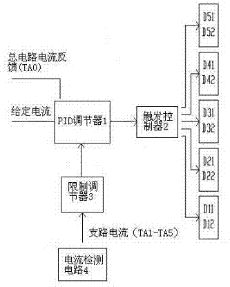
[0044] Embodiment 3: as image 3 As shown, this embodiment provides a feedback control circuit for lamination control power supply using fewer current detection devices, including a PID regulator 1, a trigger controller 2; a limit regulator 3 and The current detection circuit 4 described in Embodiment 2.

[0045] The two input terminals of the PID regulator 1 respectively input the given current and the total circuit detection current output by the total circuit current detection device TA0, the output terminal of the PID regulator 1 is connected with the trigger controller 2, and the output terminal of the trigger controller 2 is connected with the trigger controller 2. The voltage regulators in each tap branch of the laminated control power supply (the voltage regulator in the first tap branch U1 is an anti-parallel thyristor D11, D12, and the voltage regulator in the second tap branch U2 is an anti-parallel thyristor D21, D22, the voltage regulator in the third tap branch ...


PUM


Abstract

The invention relates to the field of power supply control, in particular to a current detecting circuit and a feedback control circuit applied to a laminated control power supply, and a power supply. Each transformer of the laminated control power supply has more than two parallel taps, a voltage regulator is arranged in each tap branch circuit, and a main circuit current detecting device is arranged at a common output ends of the parallel tap branch circuits. The current detection device comprises branch current computing modules, and one branch current detecting module is arranged on one of any two adjacent tap branch circuits; the branch current detecting devices and the main circuit current detecting devices are connected with the branch current computing modules; the branch circuit computing modules are used for computing current of the tap branch circuits. According to the current detecting circuit and the feedback control circuit applied to the laminated control power supply, and the power supply, a manner that a current detecting device is arranged on every one branch circuit is utilized, so that the application of current detectors in the current detecting circuits is largely reduced.

Description

technical field [0001] The invention relates to the field of power supply control, in particular to a current detection circuit, a feedback control circuit and a power supply for lamination control power supply. Background technique [0002] At present, high-power and wide-voltage range power supplies mostly adopt the stack control method. The control principle of the stack control power supply is as follows: the stack control power supply is composed of a transformer and a feedback control circuit, and the transformer includes multiple tap branches set in parallel (in this paper The mentioned tap branches and branches all represent the same technical concept), each tap branch is equipped with a voltage regulator; the feedback control circuit includes a current detection circuit, and the current detection circuit consists of the branch set in each tap branch of the transformer The current detection device and the total current detection device set at the total output end of ...

Claims


Application Information

Patent Timeline
IPC IPC(8): G01R19/00G05F1/40
Inventor 谭兵路彬
Owner SICHUAN INJET ELECTRIC CO LTD
Why Eureka
Try Eureka