
Shock-absorbing support and flight equipment using the same

A shock-absorbing bracket and flight equipment technology, applied in the direction of shock absorbers, mechanical equipment, springs/shock absorbers, etc., can solve problems such as flight instability, loss of control, increased vibration, etc.

Active Publication Date: 2017-04-19
SZ DJI TECH CO LTD
View PDF6 Cites 0 Cited by
  • Summary
  • Abstract
  • Description
  • Claims
  • Application Information

AI Technical Summary

Problems solved by technology

However, this method will cause the motor to vibrate together as a vibration source when the motor rotates, and because the side wall is relatively weak, it will drive the plastic column and the mounting plate to vibrate together when the housing vibrates, and because the structure is a cantilever type, It will increase the vibration in a disguised form, which will cause the acceleration detected by the sensing element to reach the maximum value of the measurement range when the flight equipment is in a state of emergency stop or sharp turn during high-speed flight. In the process, the vibration of the aircraft shell will cause the sensing element to detect "wrong" information, which will cause the aircraft to calculate the "wrong" flight attitude, which will greatly affect the safety performance of the aircraft
At the same time, once a collision with a foreign object is encountered during the flight, the sensing element will detect a large change in acceleration, and will perform a relatively large feedback action accordingly, resulting in an unstable flight and may cause the aircraft to Abnormal operation of the system and loss of control, causing damage to the aircraft or loss of control of the aircraft causing damage to the surrounding environment

Method used


Image

  • Shock-absorbing support and flight equipment using the same
  • Shock-absorbing support and flight equipment using the same
  • Shock-absorbing support and flight equipment using the same

Examples


Embodiment Construction

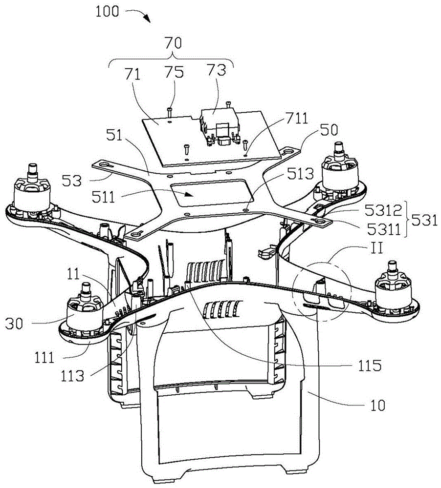
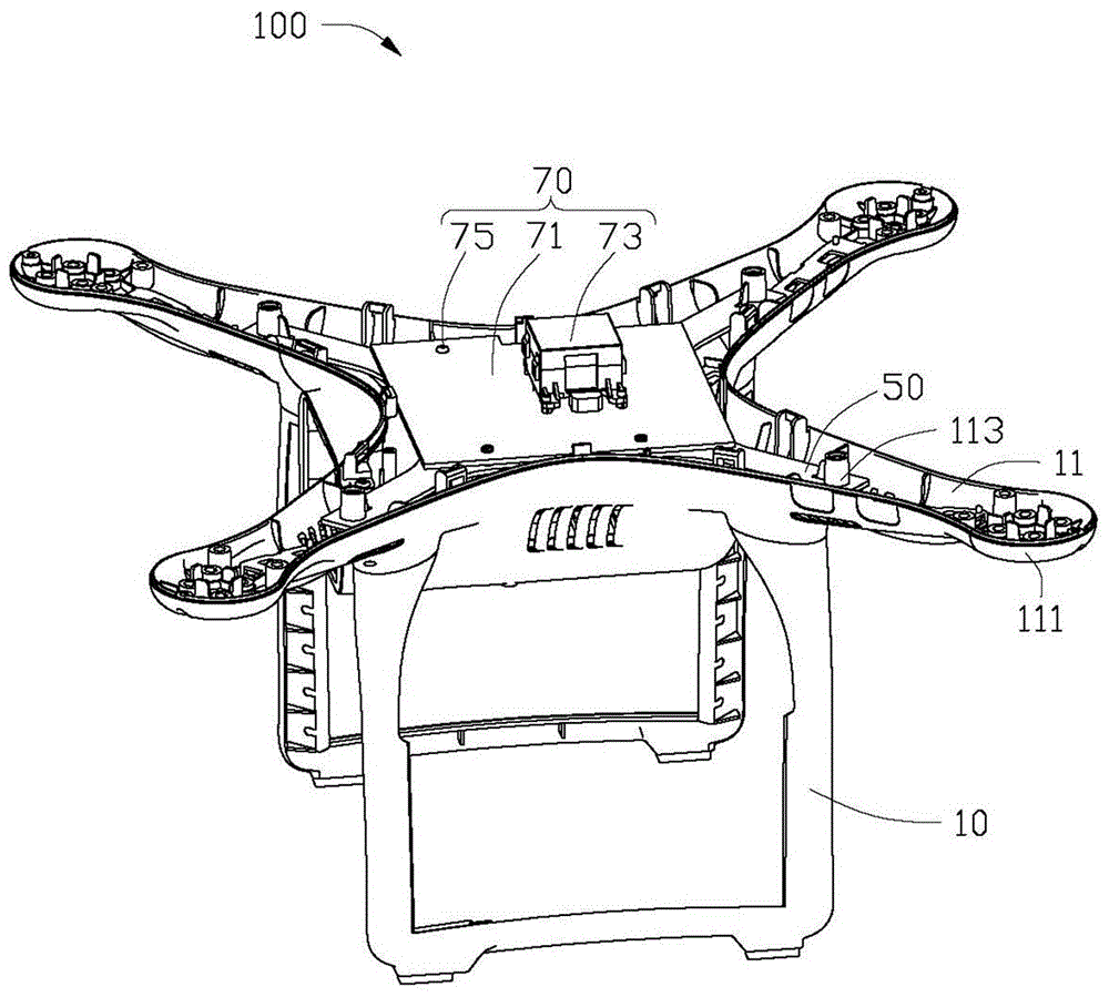
[0015] see figure 1 , the embodiment of the present invention provides a flying device 100, including a fuselage 10, at least one motor 30, a shock absorber 50 and a sensing module 70, the at least one motor 30 is installed on the fuselage 10, the The shock absorber 50 is disposed on the fuselage 10 and spaced from the motor 30 , and the sensing module 70 is fixed on the shock absorber 50 .

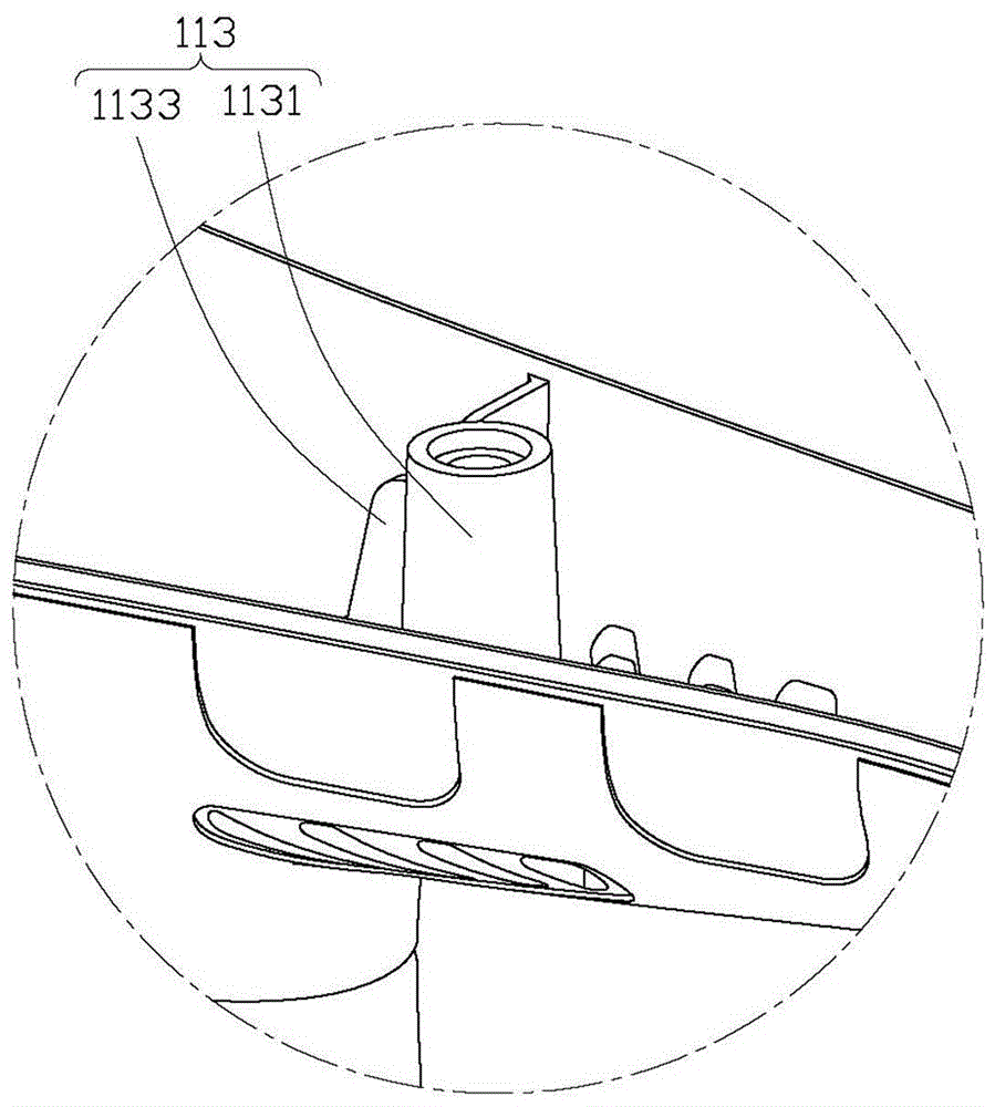
[0016] The fuselage 10 is a shell structure, which includes at least one branch cantilever 11 , at least one motor mounting portion 111 , at least one fixing portion 113 and at least one clamping portion 115 . Each motor mounting portion 111 is installed on a corresponding branch cantilever 11 for mounting the motor 30, and each of the fixing portions 113 is arranged on a corresponding branch cantilever 11 and is spaced apart from the corresponding motor mounting portion 111 . The fixing part 113 is further disposed on the bottom of the casing, and the shock absorbing bracket 50 is inst...


PUM


Abstract

The invention relates to a damping bracket and flight equipment applying the same. The flight equipment comprises a fuselage, a sensing module and the damping bracket; the fuselage comprises at least one branch cantilever and at least one fixed part correspondingly arranged at the position of the branch cantilever; the damping bracket comprises a main body part and at least one extending part formed by extending from the main body part; the main body part is used for bearing an object; the extending part is used as a fixed position; the extending part of the damping bracket is connected with the corresponding fixed part; the sensing module is connected to the fuselage through the damping bracket. According to the flight equipment, intensity of the flight equipment is reinforced by the damping bracket and the aims of damping and resisting to vibration are fulfilled.

Description

technical field [0001] The invention relates to a shock-absorbing support and flight equipment using the shock-absorbing support. Background technique [0002] In the design of the existing flight equipment, the mounting plate is generally fixed on the plastic column by screwing a long plastic column on the side wall of the fuselage shell so as to fix the mounting plate. However, this method will cause the motor to vibrate together as a vibration source when the motor rotates, and because the side wall is relatively weak, it will drive the plastic column and the mounting plate to vibrate together when the housing vibrates, and because the structure is a cantilever type, It will increase the vibration in a disguised form, which will cause the acceleration detected by the sensing element to reach the maximum value of the measurement range when the flight equipment is in a state of emergency stop, sharp turn, etc. when flying in a high-speed heading, and the flight equipment is...

Claims


Application Information

Patent Timeline
Patent Type & Authority Patents(China)
IPC IPC(8): F16F7/00B64D47/00
CPCB64D47/00F16F7/00
Inventor 冯建刚潘国秀石仁利
Owner SZ DJI TECH CO LTD
Learn More