Volume cavity regulating type exhausting device

A cavity-adjustable, volume-adjustable technology, applied in machines/engines, internal-combustion piston engines, mechanical equipment, etc., can solve problems such as the complex structure of the booster system, and achieve the effects of low fuel consumption, large air intake, and simple structure

Inactive Publication Date: 2015-07-15
SHANGHAI 01 POWER TECH
View PDF1 Cites 0 Cited by
  • Summary
  • Abstract
  • Description
  • Claims
  • Application Information

AI Technical Summary

Problems solved by technology

However, the existing turbocharging systems cannot take into account the high and low speed conditions of the engine well.
[0003] After searching the existing technical literature, it was found that Chinese patent number ZL200410050996.3, patent name: a variable modular pulse conversion supercharging device for a turbocharged diesel engine, the patented technology provides an exhaust device in the exhaust pipe The device with continuously variable volume can better take into account the high and low speed conditions of the engine; but the change of the exhaust volume in the exhaust pipe is realized by moving the moving rod up and down, which requires adding a special set The control mechanism is used to control the movement of the moving rod, so that the structure of the booster system becomes more complicated

Method used


Image

  • Volume cavity regulating type exhausting device
  • Volume cavity regulating type exhausting device
  • Volume cavity regulating type exhausting device

Examples


Embodiment

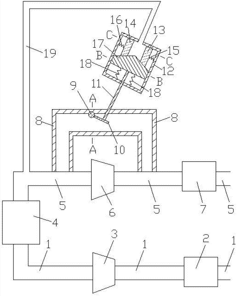
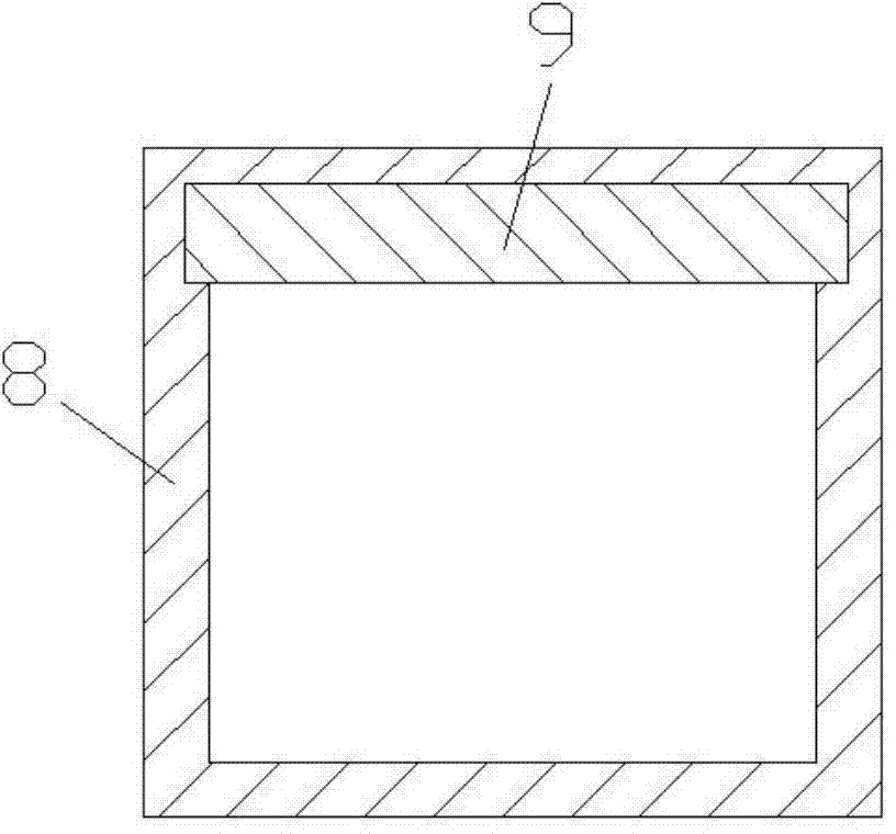
[0015] Examples of the present invention are Figure 1 to Figure 5 As shown, the present invention includes intake pipe 1, air filter 2, compressor 3, engine 4, exhaust pipe 5, turbine 6, muffler 7, air release pipe 8, rotating shaft 9, rotating plate 10, adjusting rod 11, control Cavity 12, first moving body 13, second moving body 14, first spring 15, second spring 16, third moving body 17, third spring 18, control pipe 19, air intake of engine 4 and air intake pipe 1 The air inlet and outlet of the exhaust pipe 5 are connected to the air outlet of the engine 4, the air filter 2 and the compressor 3 are connected to the intake pipe 1 in turn, the turbine 6 and the muffler 7 are connected to the exhaust pipe 5 in turn Above, the two ends of the air discharge pipe 8 are respectively connected with the exhaust pipes 5 before and after the turbine 6, the rotating shaft 9 is inlaid on the air discharging pipe 8, the rotating plate 10 is arranged in the air discharging pipe 8 and o...


PUM


Abstract

The invention belongs to a volume cavity regulating type exhausting device in the technical field of internal combustion engines. The volume cavity regulating type exhausting device comprises an air releasing pipe, a rotating shaft, a rotating plate, a regulating rod, a control cavity, a spring, moving bodies and a control pipe, wherein the rotating shaft is embedded in an exhaust circulating pipe; one end of the rotating plate and the rotating shaft are fixedly connected together; the cross sections of a first moving body, a second moving body and a third moving body are respectively provided with a slope structure and are mutually matched; one end of the control pipe is communicated with a cavity between the first moving body and the second moving body after penetrating through the upper wall surface of the control cavity; the other end of the control pipe is communicated with an exhausting pipe between an engine and a turbine. In the volume cavity regulating type exhausting device disclosed by the invention, when the load of the engine is larger, the air releasing amount of the turbine is larger; when the load of the engine is smaller, the air releasing amount of the turbine is smaller. The volume cavity regulating type exhausting device is reasonable in design, simple in structure and suitable for designing of an engine turbo-charging system.

Description

technical field [0001] The invention belongs to the technical field of internal-combustion engine design, in particular to a volume cavity-adjustable gas-bleeder capable of realizing self-regulation of turbine deflation. Background technique [0002] Turbocharging is a technology that uses the exhaust gas generated by the operation of an internal combustion engine to drive an air compressor. The main function of turbocharging is to increase the air intake of the engine, thereby increasing the power and torque of the engine and making the car more powerful. After an engine is equipped with a turbocharger, its maximum power can be increased by 40% or even higher compared with that without a supercharger. This also means that the same engine can output more power after being supercharged. Take our most common 1.8T turbocharged engine as an example. After supercharging, the power can reach the level of a 2.4L engine, but the fuel consumption is not much higher than that of a 1...

Claims


Application Information

Patent Timeline
Patent Type & Authority Applications(China)
IPC IPC(8): F02B37/18
CPCY02T10/12
Inventor 杨林羌嘉曦
Owner SHANGHAI 01 POWER TECH
Why Eureka
Try Eureka