Blast furnace iron mouth dedusting cover

A technology of dust removal cover and iron mouth, which is applied in the direction of dust collector, etc., can solve the problems of high dust collection area, the inability to lower the dust removal cover, increase the dust removal effect of the dust removal cover, etc., and achieve the effect of uniform flow of smoke and dust

Active Publication Date: 2015-07-15
BERIS ENG & RES CORP
View PDF7 Cites 0 Cited by
  • Summary
  • Abstract
  • Description
  • Claims
  • Application Information

AI Technical Summary

Problems solved by technology

However, most of the above-mentioned dust removal methods have the following disadvantages: the dust removal cover of the top suction dust removal is placed on the upper part of the iron mouth. High, affecting the dust removal effect; especially at the edge of the dust removal hood, a large amount of dust-laden smoke will diffuse out, and due to the influence of the equipment in front of the furnace, it is impossible to improve the dust removal effect by reducing the dust removal hood or increasing the dust removal hood

Method used


Image

  • Blast furnace iron mouth dedusting cover

Examples


Embodiment Construction

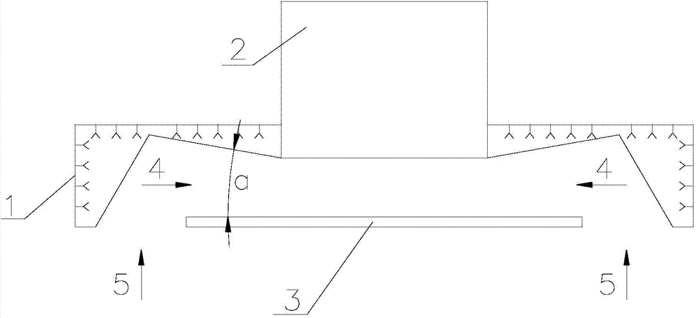
[0011] In order to better understand the purpose, structure and function of the present invention, a blast furnace iron hole dust removal hood of the present invention will be described in further detail below with reference to the accompanying drawings.

[0012] like figure 1 As shown, the blast furnace iron mouth dust removal hood of the present invention comprises a dust collecting hood body 1, a suction port 2 is formed on the top wall of the dust collecting hood body 1, a smoke guide plate 3 is horizontally arranged under the top wall, and the smoke guide plate 3 is connected with The air inlet 2 is set directly opposite. Wherein, the smoke guide plate 3 can be fixed on the dust collecting hood 1 by means of bolts or welding, and the smoke guide plate 3 can be flat or curved. Set to flat. In addition, in order to adapt to the high temperature smoke and dust sucked by the iron mouth, the inside of the dust collecting cover 1 and the smoke guide plate 3 can be provided wi...


PUM


Abstract

The invention discloses a blast furnace iron mouth dedusting cover comprising a dust collecting cover body (1), wherein an air suction opening (2) is formed in the top wall of the dust collecting cover body (1); a smoke guide plate (3) is horizontally arranged below the top wall of the dust collecting cover body (1) and is dead against the air suction opening (2); a transverse smoke dust passage (4) is formed between the smoke guide plate (3) and the top wall of the dust collecting cover body (1), and a longitudinal smoke dust passage (5) is formed between the smoke guide plate (3) and the side wall of the dust collecting cover body (1); the longitudinal smoke dust passage (5), the transverse smoke dust passage (4) and the air suction opening (2) are in fluid communication with one another in sequence; and the smoke dust at a blast furnace iron mouth can sequentially flow through the longitudinal smoke dust passage (5) and the transverse smoke dust passage (4) and then is discharged from the air suction opening (2) on the dust collecting cover body (1). The blast furnace iron mouth dedusting cover disclosed by the invention is convenient for formation of a venturi effect and can accelerate the speed of sucking away smoke dust, so that the smoke dust can be sucked more quickly and cleanly.

Description

technical field [0001] The invention relates to a blast furnace iron-making dust removal system, in particular to a top suction dust hood with a smoke guide plate. Background technique [0002] Since the 1970s, iron-making blast furnaces have developed into large-scale, and the production operation of the iron casting yard has undergone fundamental changes. The surrounding environment has a wide range of influences. If no effective control measures are taken, it will not only pollute the environment, but also seriously hinder the operation and safety of the casting yard, and also pose a great threat to the normal operation of equipment and instruments. For example: when the large blast furnace is tapping and slag, the amount of soot emitted from the surface of the molten iron launder and the molten iron tank is about 400-700g per ton of molten iron, and the dust concentration of the flue gas is 150-1500mg / m2 3 between; SiO in the soot during tapping 2 The content is about...

Claims


Application Information

Patent Timeline
Patent Type & Authority Applications(China)
IPC IPC(8): C21B7/22
Inventor 师磊
Owner BERIS ENG & RES CORP
Why Eureka
Try Eureka