
Voltage regulation method based on inverter power coordination control

A coordinated control and voltage regulation technology, applied in the direction of AC network voltage adjustment, irreversible DC power input conversion to AC power output, electrical components, etc., can solve power loss, photovoltaic power supply can not participate, line terminal voltage and rated value big deviation etc.

Active Publication Date: 2015-07-08
STATE GRID CORP OF CHINA +3
View PDF1 Cites 25 Cited by
  • Summary
  • Abstract
  • Description
  • Claims
  • Application Information

AI Technical Summary

Problems solved by technology

[0006] The disadvantages of the above several voltage regulation methods are: although the APC method has a good voltage regulation effect, it is at the cost of reducing the utilization rate of light energy; the Q(P) control strategy adjusts its reactive power according to the active power output by the photovoltaic power supply. Power, when the active power output by photovoltaics is large, but still less than the user load, that is, P load >P pv However, according to the Q(P) strategy, the photovoltaic power supply will absorb a large amount of reactive power to reduce the voltage, which will cause additional power loss; The Q(U) control strategy directly adjusts the reactive power according to the voltage amplitude of the grid-connected point, which overcomes the defects of the Q(P) strategy, but because the voltage amplitude of each access point on the line is different, the line close to the transformer The voltage at the head end is almost constant, and the voltage at the end of the line deviates greatly from the rated value. This will often cause the photovoltaic power supply at the end of the line to absorb reactive power to the maximum, and the photovoltaic power supply at the head end of the line cannot participate in voltage regulation at all. Phenomenon

Method used


Image

  • Voltage regulation method based on inverter power coordination control
  • Voltage regulation method based on inverter power coordination control
  • Voltage regulation method based on inverter power coordination control

Examples


Embodiment Construction

[0033] In order to facilitate those of ordinary skill in the art to understand and implement the present invention, the present invention will be described in further detail below in conjunction with the accompanying drawings and embodiments. It should be understood that the implementation examples described here are only used to illustrate and explain the present invention, and are not intended to limit this invention.

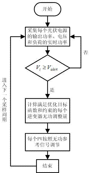
[0034] The control structure of this method includes a central controller and multiple bottom controllers, relying on the communication link, the central controller and each bottom controller carry out signal transmission, and the bottom controllers cannot communicate with each other, according to the instructions of the central controller action;

[0035] In this embodiment, nodes are a concept of topology. Some nodes are distributed with photovoltaic power sources, and some are not. This should be determined according to the actual situation. Number is equ...


PUM


Abstract

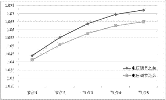
The invention discloses a voltage regulation method based on inverter power coordination control. The method comprises the steps that during one sampling period, a constrained and optimized mathematical model is used for conducting power coordination control over photovoltaic inverters; the objective function (shown in the specification) of the constrained and optimized mathematical model is the minimum of the sum of reactive power output by all photovoltaic power sources, and the constraint conditions include the inverter capacity constraint, the node flow constraint, the node voltage constraint and the inverter power adjustment weight constraint; on the condition of meeting all the proposed constraint conditions, a set of reactive power adjustment quantities of the minimum sum of the reactive power output by all the photovoltaic power sources are solved through an optimization algorithm and serve as reactive power reference values for coordination control over all the photovoltaic inverters, and voltage adjustment of grid-connection points in an area is achieved. By means of the method, on the premise of not reducing the photovoltaic output active power, the voltage adjustment capacity of each inverter can be fully utilized, and the situation that unnecessary lien power losses are caused by output of excessive reactive power can be avoided.

Description

technical field [0001] The invention belongs to the technical field of distributed photovoltaic grid-connected power generation, and specifically relates to a method for providing voltage regulation for a large number of distributed photovoltaics connected to a low-voltage distribution network. Background technique [0002] With the large-scale access of distributed photovoltaics in the distribution network, a large number of active reverse currents cause overvoltage problems at the grid-connected point. Making full use of the active and reactive power adjustment capabilities of the inverter can effectively suppress the voltage limit of the grid-connected point. At present, there are several methods of voltage regulation based on the inverter as follows. [0003] (I) Active power reduction, that is, APC (active power curtailment), achieves the purpose of reducing the grid-connected point voltage by reducing the active power generated by the photovoltaic power supply during t...

Claims


Application Information

Patent Timeline
IPC IPC(8): H02J3/38H02J3/16H02M7/42
CPCH02J3/16H02J3/383Y02E10/56Y02E40/30
Inventor 孙鹏罗明武周友斌周鲲鹏孙朝霞刘天慈邓长虹刘辉杨威郑峰张志刚
Owner STATE GRID CORP OF CHINA
Learn More