
Seismic 3D Velocity Scanning and Focusing Imaging Method

A technology of focused imaging and speed scanning, which is applied in the field of engineering geophysical prospecting, can solve the problems of stacking speed changes and inability to perform high-precision imaging, and achieve the effect of improving the signal-to-noise ratio

Active Publication Date: 2017-07-21
ZHENGZHOU UNIV
View PDF5 Cites 0 Cited by
  • Summary
  • Abstract
  • Description
  • Claims
  • Application Information

AI Technical Summary

Problems solved by technology

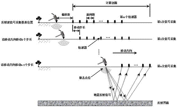
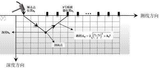
[0003] The technical problem to be solved by the present invention is to provide a seismic three-dimensional wave velocity scanning focusing imaging method, based on the basic principle of the diffraction scanning migration imaging method, to scan any section point under the scanning section with a certain range of velocity, and then Apply 3D image processing technology to perform high-precision superimposed imaging on the scanning section, and solve the problem that high-precision imaging cannot be performed due to changes in superimposed speed

Method used


Image

  • Seismic 3D Velocity Scanning and Focusing Imaging Method
  • Seismic 3D Velocity Scanning and Focusing Imaging Method
  • Seismic 3D Velocity Scanning and Focusing Imaging Method

Examples


specific Embodiment

[0072] The geological survey data of a certain tunnel on the “Lanyu Railway” showed that there are unfavorable geological conditions such as karst at the tunnel axis, and other detection methods cannot be used to determine its specific location. After the tunnel construction is completed, seismic imaging is performed along the axis on the inner floor of the tunnel.

[0073] Using the present invention to perform three-dimensional wave velocity scanning and focusing imaging on the seismic recording signal of the karst abnormal exploration area in the tunnel, the detection result is as follows Picture 11 Shown. by Picture 11 Known:

[0074] 1. The karst abnormal area in the imaging map is obvious and consistent with the actual verification results.

[0075] 2. For areas with more complex underground geological conditions, the vertical and horizontal speed changes greatly, and the three-dimensional scanning focus imaging method can better reflect the actual conditions of the undergro...


PUM


Abstract

The invention relates to a seismic three-dimensional wave velocity scanning focusing imaging method. The steps are as follows: collecting seismic reflection wave signal records by means of coverage observation; extracting common reflection point signal records according to the seismic reflection wave signal records; performing velocity scanning on the imaging calculation section, The energy map of the calculated profile is obtained; the profile energy maps scanned at different speeds are superimposed, and the three-dimensional image technology is used for focused imaging. The invention scans and images the velocity within a certain range, realizes the velocity layered scanning, avoids losing a lot of useful information due to directly taking the maximum value after scanning and stacking, and directly performs high-precision imaging on the complex changing wave velocity profile under arbitrary terrain conditions; It can be widely used in water conservancy, roads, bridges, tunnels and municipal prediction and detection, as well as oil, gas, coal and mineral exploration and prediction.

Description

Technical field [0001] The invention relates to the technical field of engineering geophysical prospecting, in particular to a seismic three-dimensional wave velocity scanning focusing imaging method. Background technique [0002] The processing of seismic reflection data can generally be divided into four stages: preprocessing, parameter analysis processing, conventional processing and data interpretation processing. In the process of data interpretation and processing, seismic imaging is the final stage of many processing methods. Currently, pre-stack time migration imaging, pre-stack depth migration imaging and diffraction scan migration imaging based on ray theory are commonly used. Pre-stack time migration can only solve the problem of superposition of common reflection points, but cannot solve the problem that the imaging point and the underground diffraction point do not overlap. Therefore, pre-stack time migration is mainly used in areas where the underground lateral vel...

Claims


Application Information

Patent Timeline
Patent Type & Authority Patents(China)
IPC IPC(8): G01V1/28
Inventor 王运生乐金朝乔东祥杜雪芹彭宏勋王瑞山王艺杰张晓军贺志彬李蓬王志刚门博杜晓甫王晓丽蒋蕾赵宏涛艾跃宗
Owner ZHENGZHOU UNIV
Learn More