
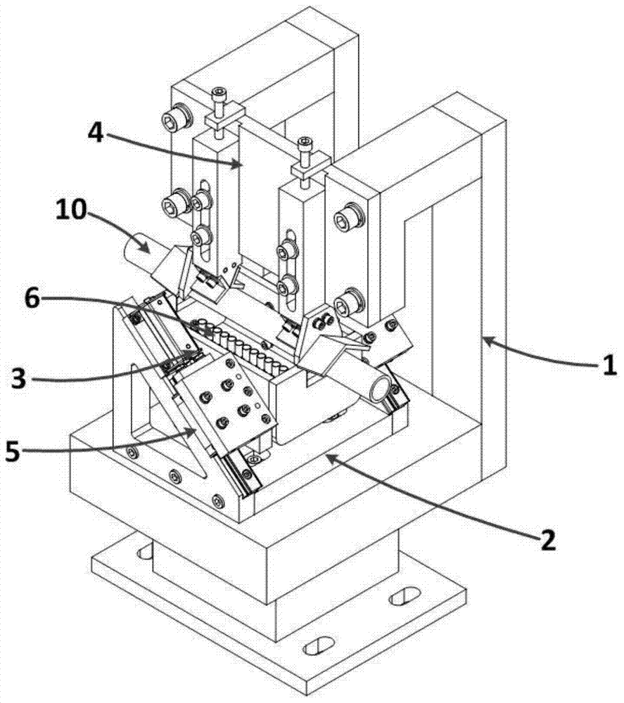
A steel pipe ultrasonic thickness measuring device

A steel pipe and ultrasonic technology, applied in measuring devices, using ultrasonic/sonic/infrasonic waves, instruments, etc., can solve the problems of potential safety hazards, difficulty in meeting high-speed detection of steel pipes, and affecting detection efficiency, etc., to achieve high-speed automation and easy high-speed automation , the effect of broad application prospects

Active Publication Date: 2017-06-30
WUHAN HUAYUYIMU TESTING EQUIP CO LTD +1
View PDF4 Cites 0 Cited by
  • Summary
  • Abstract
  • Description
  • Claims
  • Application Information

AI Technical Summary

Problems solved by technology

[0003] At present, there are mainly ray method, eddy current method, and laser method for measuring the thickness of steel pipes. The above methods all have various shortcomings: the ray method has no special requirements for the workpiece, but because it requires a radioactive source, there are potential safety hazards; the eddy current method uses high-frequency reflection The principle of the eddy current sensor does not need to touch the workpiece, and it can be detected in harsh environments, but the thickness of the workpiece and the change in resistivity will affect its measurement accuracy; the laser method has the characteristics of high directivity and high coherence, but it is not suitable for the The detected object is stationary or has a limited moving speed, which affects the detection efficiency
However, as the output of steel pipes increases, the traditional portable ultrasonic thickness gauge is difficult to meet the needs of high-speed detection when steel pipes are moving at high speed due to their low efficiency.
[0005] In addition, it is difficult to ensure that the ultrasonic probe is aligned with the lower busbar of the steel pipe during the detection of the existing ultrasonic testing device, which reduces the accuracy of the measurement

Method used


Image

  • A steel pipe ultrasonic thickness measuring device
  • A steel pipe ultrasonic thickness measuring device
  • A steel pipe ultrasonic thickness measuring device

Examples


Embodiment Construction

[0030] In order to make the object, technical solution and advantages of the present invention clearer, the present invention will be further described in detail below in conjunction with the accompanying drawings and embodiments. It should be understood that the specific embodiments described here are only used to explain the present invention, not to limit the present invention. In addition, the technical features involved in the various embodiments of the present invention described below can be combined with each other as long as they do not constitute a conflict with each other.

[0031] figure 1 It is a schematic diagram of the principle of ultrasonic thickness measurement in the present invention. The ultrasonic probe 621 generates ultrasonic waves under the action of the excitation source, and the ultrasonic sound beam propagates through water. When the sound beam enters the steel pipe 10, multiple reflections are formed between the inner wall and the outer wall of th...


PUM


Abstract

The invention discloses a steel pipe ultrasonic thickness measurement device which comprises a machine frame, a supporting base, a steel pipe tracking assembly and a pipe pressing limiting assembly. The supporting base is installed on the machine frame. The steel pipe tracking assembly is installed on the supporting base, and comprises a tracking device and a detecting device. The tracking device comprises a cylinder, a linear guide rail and a slide block. The detecting device comprises a water tank and an ultrasonic measuring head device. The cylinder and the linear guide rail are both installed on the supporting base. The slide block is installed on the linear guide rail. An output shaft of the cylinder is fixedly connected with the slide block. The slide block is fixedly connected with the water tank so as to drive the water tank to get close to or get away from the pipe pressing limiting assembly. The pipe pressing limiting assembly is installed on the machine frame and used in cooperation with the water tank for clamping and limiting a steel pipe. Through the combination of a steel pipe detection production line actual detection procedure, the water tank is in an initial position when the steel pipe does not enter the detection position, the water tank drives the ultrasonic measuring head device to enter the detection position when the steel pipe enters the detection position, and the high-speed detection during the high-speed movement of the steel pipe can be achieved.

Description

technical field [0001] The invention belongs to the field of nondestructive testing equipment, and more specifically relates to an ultrasonic thickness measuring device for steel pipes. Background technique [0002] As a deep-processed metal product with complex technology, seamless steel pipe has high yield strength and stress corrosion resistance in performance. At the same time, as a hollow section, it can transport fluids such as oil, so it is widely used in power stations and boilers. , construction, petrochemical and petroleum industries. As the demand for seamless steel pipes continues to increase, the quality of products is becoming more and more important. Especially in harsh working conditions such as high temperature and high pressure, there are higher requirements for the quality of seamless steel pipes. Thickness is one of the important detection indicators of steel pipes. It is a parameter to be precisely controlled and guaranteed, and it is very important to...

Claims


Application Information

Patent Timeline
Patent Type & Authority Patents(China)
IPC IPC(8): G01B17/02
CPCG01B17/02
Inventor 康宜华王哲
Owner WUHAN HUAYUYIMU TESTING EQUIP CO LTD
Learn More