


Quick Research
Generate reliable direction feasibility study reports for your R&D in just a few steps.

Technical Q&A
Discover and master advanced knowledge NOW. Basics, ideas, possibilities, all at once.

Find Solutions
As an expert in R&D theories, this can generate solutions to your technical problems instantly.

Evaluate Feasibility
Analyze your overall solution with one click, know your potential R&D risks in advance.

Monitor Landscape
Get weekly tech updates, stay abreast of the latest tech innovations and key insights.
Flaring test tool
A flaring test and tooling technology, used in measuring devices, instruments, scientific instruments, etc., can solve the problems of flaring amount and design flaring amount error, and achieve the effect of improving accuracy, convenient processing and improving versatility
- Summary
- Abstract
- Description
- Claims
- Application Information
AI Technical Summary
Problems solved by technology
Method used
Image

Examples
specific Embodiment 1
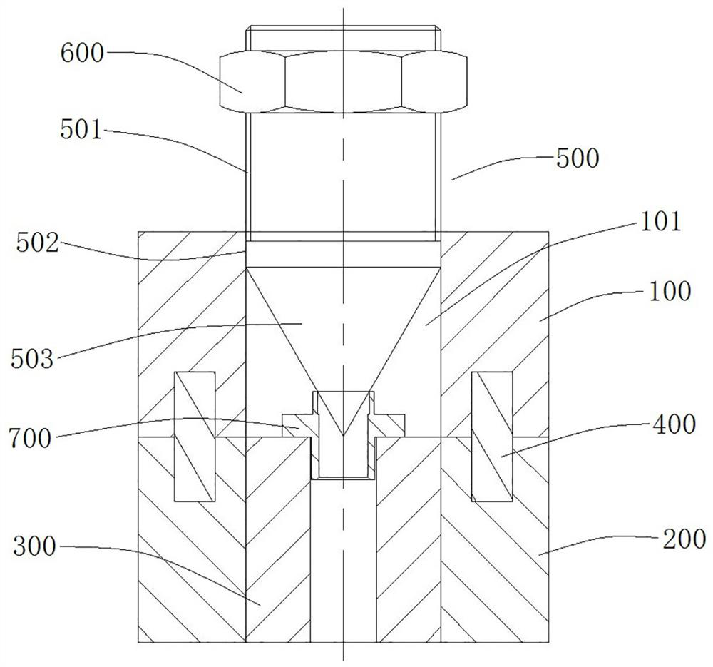
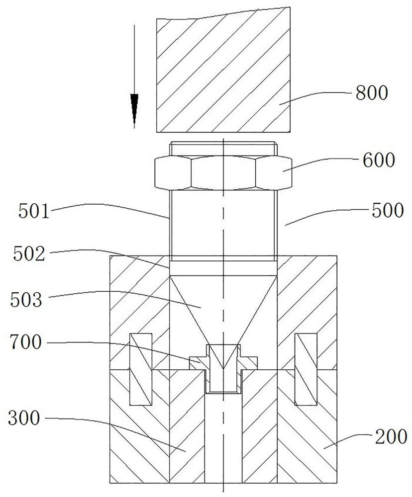
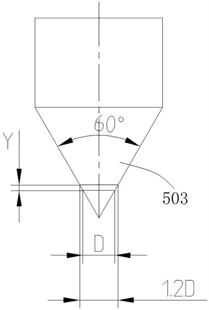
[0040] Such as Figure 1 to Figure 7 As shown, the flaring test tool is used to quantitatively flaring the sample, which not only improves the flaring efficiency, but also ensures that the designed flaring amount is achieved. In this embodiment, the expansion of the expansion end of the expansion nut 700 by 1.2 times is taken as an example for illustration.
[0041] The flaring test tooling includes a support, which is used to position and support the flaring nut 700 and guide the top core 500 to penetrate, such as figure 1 and figure 2 As shown, the support includes an upper support 100 and a lower support 200, the upper support 100 is positioned and supported on the lower support 200 by at least two positioning pins 400, that is to say, the upper support 100 will not be horizontally opposite Translation or rotation occurs on the lower support 200 . The lower support 200 is provided with a base through hole (not marked in the figure) which penetrates up and down, and the ...
Embodiment 1
[0050] In Example 1, there are positioning holes on the base for the fitting and penetration of the sample. In this embodiment, the positioning hole may be a blind hole. When the sample is a tube / cylinder and there is no outer retaining edge, replace the positioning hole on the base with a positioning column for the tube / cylinder to fit properly.
specific Embodiment 3
[0052] In Embodiment 1, the base is separately mounted on the lower support. In this embodiment, the base can be integrally formed on the lower support, that is to say, the support part at this time can be a part of the lower support that is provided with a positioning hole or a positioning column.
PUM
 Abstract
Description
Claims
Application Information
 - R&D Engineer
- R&D Manager
- IP Professional
- Industry Leading Data Capabilities
- Powerful AI technology
- Patent DNA Extraction
Browse by: Latest US Patents, China's latest patents, Technical Efficacy Thesaurus, Application Domain, Technology Topic, Popular Technical Reports.
© 2024 PatSnap. All rights reserved.Legal|Privacy policy|Modern Slavery Act Transparency Statement|Sitemap|About US| Contact US: help@patsnap.com