A device for producing fiber-reinforced cement lightweight porous partition wall slats

A technology for strengthening cement and porous partition walls, which is applied to ceramic molding machines, ceramic molding workshops, manufacturing tools, etc., can solve the problems of intermittent floor space occupied by original wallboards and high production environment requirements, and achieve stable work, easy cleaning, non-deformable effect

Inactive Publication Date: 2017-03-22
裴庭胜
View PDF1 Cites 0 Cited by
  • Summary
  • Abstract
  • Description
  • Claims
  • Application Information

AI Technical Summary

Problems solved by technology

[0005] The purpose of the present invention is to provide a device for producing fiber-reinforced cement lightweight porous partition wall slats, which solves the problems of discontinuity in the production of original wall panels, large floor space during original production, and high requirements for the production environment.

Method used


Image

  • A device for producing fiber-reinforced cement lightweight porous partition wall slats
  • A device for producing fiber-reinforced cement lightweight porous partition wall slats
  • A device for producing fiber-reinforced cement lightweight porous partition wall slats

Examples


Embodiment 1

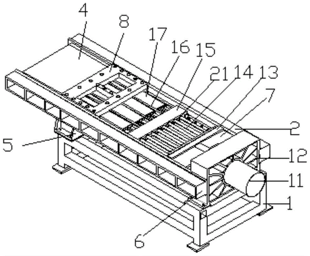
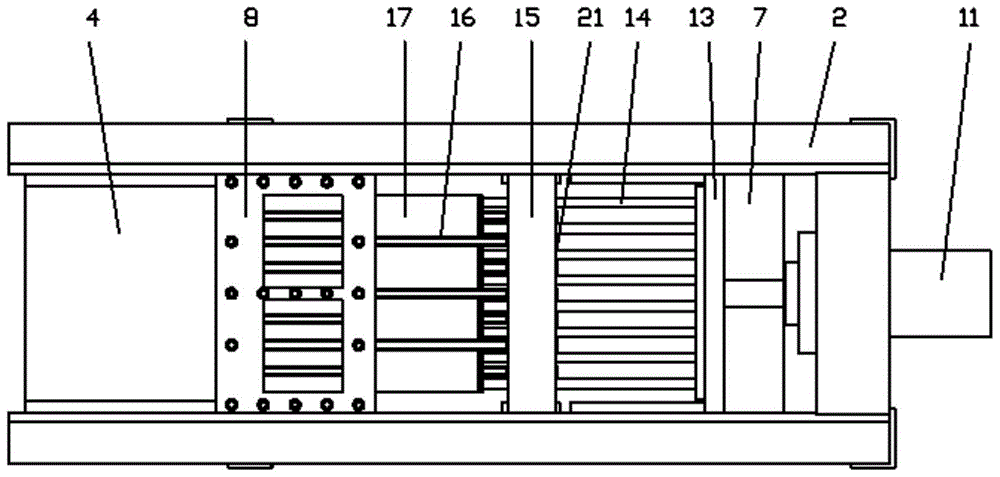
[0026] Pull out the mold core connection plate 10 in the mold forming device 4 and connect the conduit 25 as a whole, and connect the circular conduit 25 and the mold core connection plate 10 matched therewith.

[0027]The material is transported to the feeding bin 8 through the screw feeding device 9 . The hydraulic cylinder 11 works, and the piston of the hydraulic cylinder drives the connecting plate 7 to move, and the connecting plate 7 drives the push plate 13, sixteen guide posts 14, and the piston group 17 to reciprocate. When the piston group 17 advances the feed bin 8, the material is extruded. The material enters the mold forming device 4, solidifies and forms in the forming device 4. When the piston group 17 leaves the feeding bin 8 on the return journey, the material continues to enter and be transported to the feeding bin 8 through the screw feeding device 9 . So back and forth, the product is continuously generated. The product is sent out by the feeding devic...

Embodiment 2

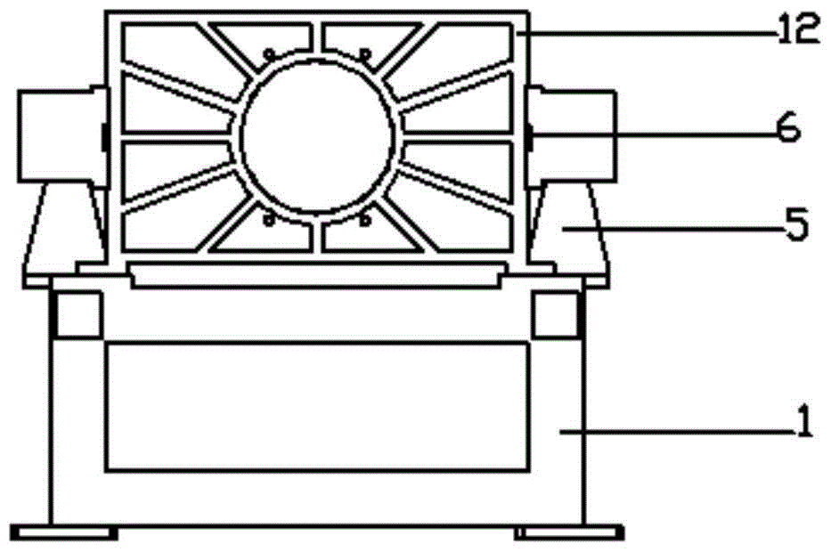
[0030] Pull out the mold core connecting plate 10 in the mold molding device 4 and connect the conduit 25 into a whole, connect the conduit 25 in the shape of a cuboid to the core connecting plate 10 that matches it, and insert one end of the core connecting plate 10 into the On the mold holder 16. Then start producing the product again.

[0031] The material is transported to the feeding bin 8 through the screw feeding device 9 . The hydraulic cylinder 11 works, and the piston of the hydraulic cylinder drives the connecting plate 7 to move, and the connecting plate 7 drives the push plate 13, sixteen guide posts 14, and the piston group 17 to reciprocate. When the piston group 17 advances the feed bin 8, the material is extruded. The material enters the mold forming device 4, solidifies and forms in the forming device 4. When the piston group 17 leaves the feeding bin 8 on the return journey, the material continues to enter and be transported to the feeding bin 8 through t...


PUM


Abstract

The invention discloses a device for generating a fiber reinforced cement light porous partition wall batten. The device for generating the fiber reinforced cement light porous partition wall batten comprises a machine frame, two girders, guide rails, a connection plate, a drive device, an overall guiding and fixing push device, a feeding device and a mold shaping device, wherein the drive device is arranged on the machine frame, one end of each girder is fixed on the drive device, the other end of each girder is fixed at one end of the machine frame, far away from the drive device, through a cushion block, the two girders are parallel, the guide rails are respectively arranged on the inner sides of the two girders, the overall guiding and fixing push device, the feeding device and the mold shaping device are sequentially arranged on the guide rails, the overall guiding and fixing push device slides along the guide rails, one end of the overall guiding and fixing push device is connected with the drive device through the connection plate, the other end of the overall guiding and fixing push device is connected with the feeding device, the feeding device is connected with the mold shaping device, and a round hole is formed in the center of the connection plate. The device for generating the fiber reinforced cement light porous partition wall batten solves the problems that original wall board production is discontinuous, a large area is occupied in the original production, the original production has a high demand for a production environment and the like.

Description

technical field [0001] The invention relates to the field of building material equipment, in particular to an equipment for producing fiber-reinforced cement lightweight porous partition wall strips. Background technique [0002] In construction projects, solid clay bricks should be used as little as possible. In order to protect cultivated land, save energy, and protect the environment, the use of industrial ash waste is in line with the national policy of wall material innovation and building energy conservation, improving the utilization rate of building area and reducing the weight of buildings. It is also the direction of housing industry development. For this reason, new building wall materials have developed rapidly in recent years, and a variety of lightweight wall panels have emerged, such as hollow wall panels such as industrial ash concrete porous glass fiber reinforced cement lightweight porous partition wall panels. [0003] At present, the lightweight wallboar...

Claims


Application Information

Patent Timeline
Patent Type & Authority Patents(China)
IPC IPC(8): B28B15/00B28B3/20
CPCB28B3/20B28B15/00
Inventor 裴庭胜
Owner 裴庭胜
Why Eureka
Try Eureka