
Magnetic suspension momentum sphere

A momentum ball and magnetic levitation technology, applied in the aerospace field, can solve the problems of complex suspension control, high cost, and complicated manufacturing, and achieve the effects of simple suspension control, simple and compact structure, and light weight.

Active Publication Date: 2015-07-01
TSINGHUA UNIV +1
View PDF7 Cites 22 Cited by
  • Summary
  • Abstract
  • Description
  • Claims
  • Application Information

AI Technical Summary

Problems solved by technology

From the perspective of reducing satellite size, increasing satellite payload, and reducing costs, the shortcomings of existing momentum wheels hinder the miniaturization and cost reduction of satellites to a certain extent
[0005] The magnetic levitation momentum ball can solve the above-mentioned problems of the momentum wheel. The existing magnetic levitation momentum ball technology is mostly a permanent magnetic synchronous magnetic levitation momentum ball, which is complicated to manufacture and expensive, which is not conducive to miniaturization and low cost, which limits its application.
Most of the existing inductive magnetic levitation momentum balls cannot realize the integration of levitation and drive, which is not conducive to the attitude control of the spacecraft; moreover, most of the levitation is realized by suction, which is not an inherently stable levitation system, and the levitation control is complicated

Method used


Image

  • Magnetic suspension momentum sphere
  • Magnetic suspension momentum sphere
  • Magnetic suspension momentum sphere

Examples


Embodiment Construction

[0017] The embodiments of the present invention will be further described in detail below in conjunction with the accompanying drawings.

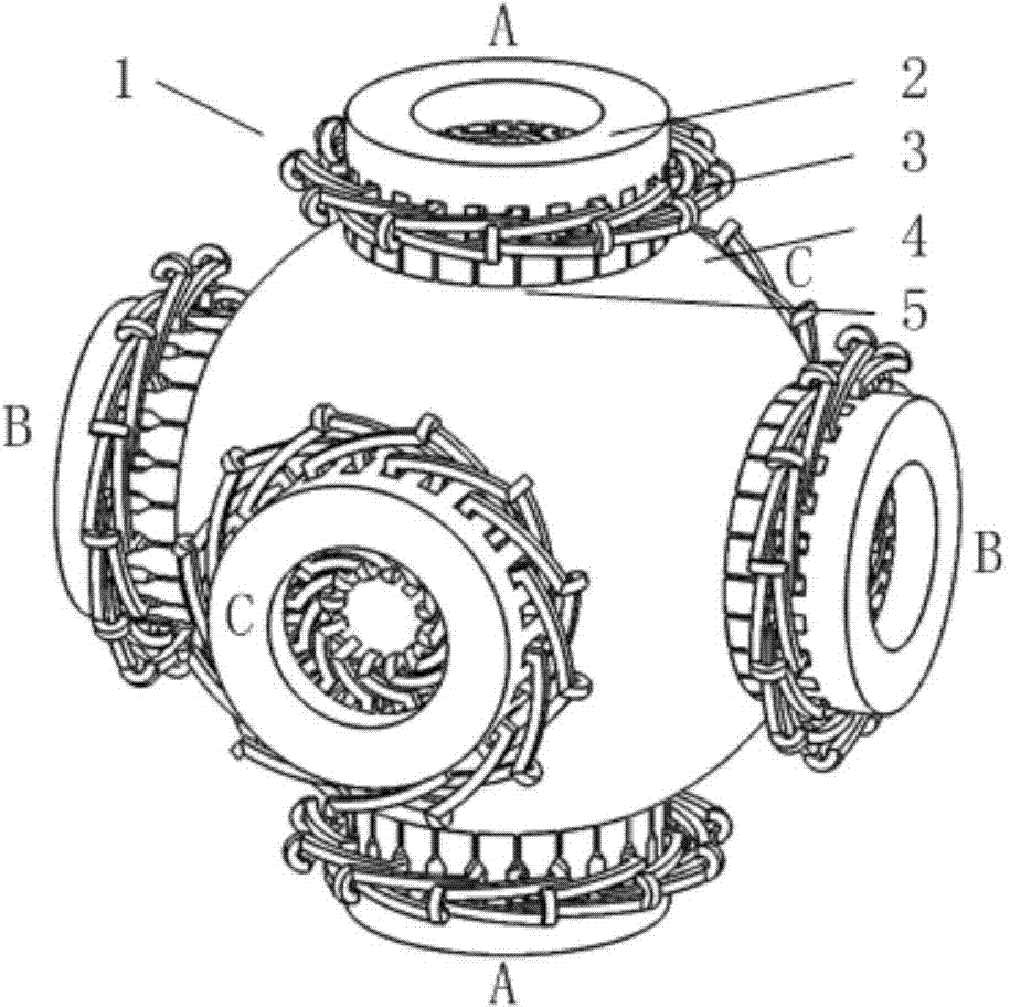
[0018] figure 1 It is a schematic diagram of an embodiment of a magnetic levitation momentum ball provided by the present invention, which includes a mover 4 and six stators 1 , and an air gap 5 is formed between each stator 1 and mover 4 . The mover 4 is in the shape of a spherical shell, and the six stators 1 are divided into three groups, respectively numbered A, B, and C. Each group includes two stators with the spherical center of the mover 4 as the center of symmetry, and the three groups of stators The axes are orthogonal to each other; each stator 1 includes a stator core 2 and a coil array 3 .

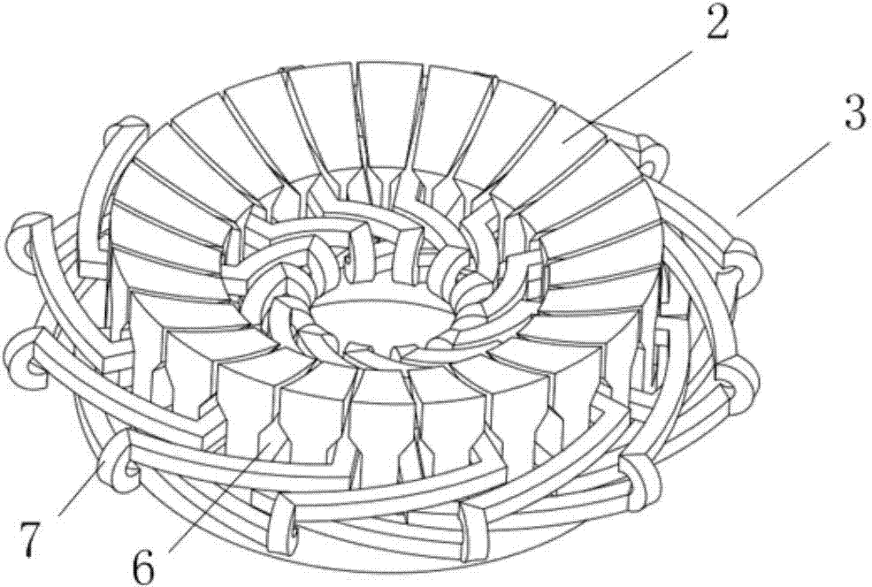
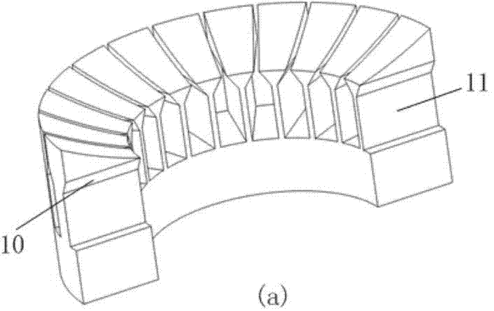
[0019] figure 2 It is a schematic diagram of the stator structure in the embodiment. The upper surface of the stator core 2 is a spherical surface, and there are through slots 6 on the circumference. Surface type through groove 12, such...


PUM


Abstract

The invention discloses a magnetic suspension momentum sphere used for spacecraft attitude adjustment. The magnetic suspension momentum sphere comprises a spherical-shell-shaped rotor and three groups of stators. Each group of stators comprises two stators taking the sphere center of the rotor as the symcenter, and axes of the three groups of stators are mutually orthogonal. Each stator comprises a stator core and a coil array. Inner surfaces, matched with the rotor, of the stator cores are spherical surfaces, and air gaps are reserved between the spherical surfaces and the outer surface of the rotor. Through grooves are formed in the stator cores radially and are evenly distributed on the circumferences of the stator cores. The coil arrays refer to disc-type motor stator windings. Two effective sides of each coil in each coil array are placed in two through grooves of the corresponding stator core respectively. The magnetic suspension momentum sphere has the advantages that cost is low, suspension and rotation driving are integrated, the magnetic suspension momentum sphere is simple and compact in structure, small in size and low in mass and belongs to fixed stable suspension, and suspension control is simple.

Description

technical field [0001] The invention relates to the field of aerospace technology, in particular to a magnetic levitation momentum ball used for attitude adjustment of spacecraft. Background technique [0002] Due to the effects of various disturbance forces in space, on-orbit spacecraft usually have a requirement for attitude stability; for some types of satellites such as reconnaissance satellites, there is also a need for high-precision attitude adjustment. Therefore, the driving device used for spacecraft attitude stabilization and precise adjustment is an important part of spacecraft development. [0003] The momentum wheel adopting the principle of momentum moment conservation is the most commonly used driving component for attitude adjustment at present. The existing mature technology is the mechanical ball bearing momentum wheel. Although the new generation of magnetic suspension momentum wheel overcomes some shortcomings of the mechanical ball bearing momentum wheel...

Claims


Application Information

Patent Timeline
Patent Type & Authority Applications(China)
IPC IPC(8): H02K16/00H02N15/00B64G1/24
CPCB64G1/24H02K16/00H02N15/00B64G1/283G05D1/08H02K2201/03
Inventor 张鸣朱煜陈安林杨开明成荣刘峰胡金春胡楚雄徐登峰穆海华
Owner TSINGHUA UNIV
Learn More