How to Replace Butterfly Valve by Vacuumizing Transformer with Oil

A transformer and vacuuming technology, which is applied in the manufacture of inductors/transformers/magnets, switchgear, electrical components, etc., can solve the problems of economic losses, troublesome preparations, and long power outages in industrial enterprises of users, so as to reduce economic losses and reduce Power outage time, time saving effect

Active Publication Date: 2017-04-26
STATE GRID CORP OF CHINA +1
View PDF2 Cites 1 Cited by
  • Summary
  • Abstract
  • Description
  • Claims
  • Application Information

AI Technical Summary

Problems solved by technology

[0005] (1) The preparation work is cumbersome, and large oil tanks and large oil filters need to be transported
[0006] (2) The work is cumbersome. It takes a lot of time to put the transformer oil below the butterfly valve, and it takes a long time to vacuumize and fill the oil. Finally, it takes more than a day to let the oil stand still for exhaust.
[0007] (3) Due to the long time required for various tasks, the entire work will take three to five days to complete, resulting in long power outages, which will bring great economic losses to users, especially industrial enterprises

Method used


Image

  • How to Replace Butterfly Valve by Vacuumizing Transformer with Oil
  • How to Replace Butterfly Valve by Vacuumizing Transformer with Oil

Examples


Embodiment Construction

[0042] The specific embodiments of the present invention will be described in detail below with reference to the accompanying drawings.

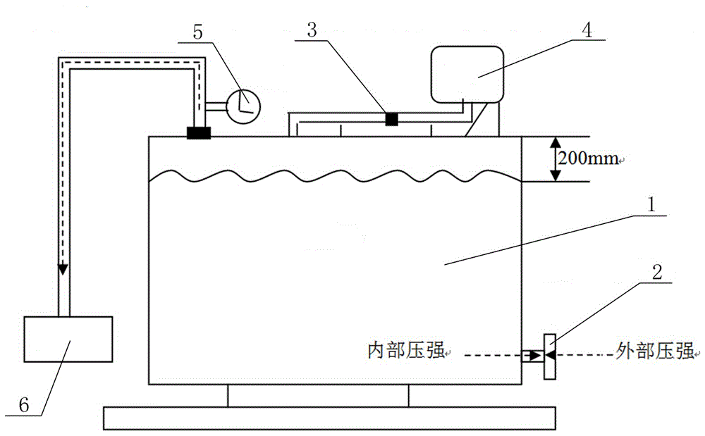
[0043] A method for replacing a butterfly valve by vacuuming a transformer with oil, such as figure 1 shown, including the following steps:

[0044] (1) Close the normal butterfly valve 3 between the oil pillow 4 and the transformer body, close all the normal butterfly valves between the transformer body and the radiator, and close the normal butterfly valve between the clean oil tank and the transformer body.

[0045] (2) Part of the main body oil 1 in the transformer is released from the oil drain port, so that the oil level drops below the oil pillow, and further drops by 200mm to make necessary space for vacuuming and pressure reduction.

[0046] (3) Remove the thermometer at the thermometer port and vacuumize the connecting tube of the thermometer.

[0047] (4) Connect the vacuum pump 6 to evacuate.

[0048] (5) Pay attention to the ...


PUM


Abstract

The invention relates to a large oil power transformer maintenance process in a power system, in particular to a method for replacing a butterfly valve of a transformer through oil-carrying vacuumizing. The method is reasonable in design, and a vacuum pump is used for vacuumizing, so that replacement work of the butterfly valve can be completed while the transformer does not release oil completely, time for the whole replacement process is saved, outage time can be reduced effectively, power sale quantity is increased, economic loss is lowered, working efficiency is improved, waste of manpower resources is reduced, manpower resource expense is saved, and transport expense caused by transporting of large equipment is reduced.

Description

technical field [0001] The invention relates to a maintenance process for a large oil power transformer in a power system, in particular to a method for replacing a butterfly valve by vacuuming the transformer with oil. Background technique [0002] The power transformer is the core equipment of the substation, and the interior is full of transformer oil. The power regulations strictly stipulate that the transformer during installation and operation must not leak oil, so as not to affect the safe operation of the power grid. Transformer oil leakage has always been a prominent problem in the operation of transformers. A considerable proportion of transformer oil leakage is leakage of butterfly valves, mainly due to quality problems of gaskets, installation problems and aging of gaskets caused by long-term operation. [0003] At present, the process of replacing the butterfly valve of the transformer under the traditional process is cumbersome, which is divided into: construc...

Claims


Application Information

Patent Timeline
Patent Type & Authority Patents(China)
IPC IPC(8): H02B3/00H01F41/00
CPCH01F41/00H02B3/00
Inventor 贾志刚解伟邵亮张江韩阳
Owner STATE GRID CORP OF CHINA
Why Eureka
Try Eureka