
Geological interface structure detection method, device and system

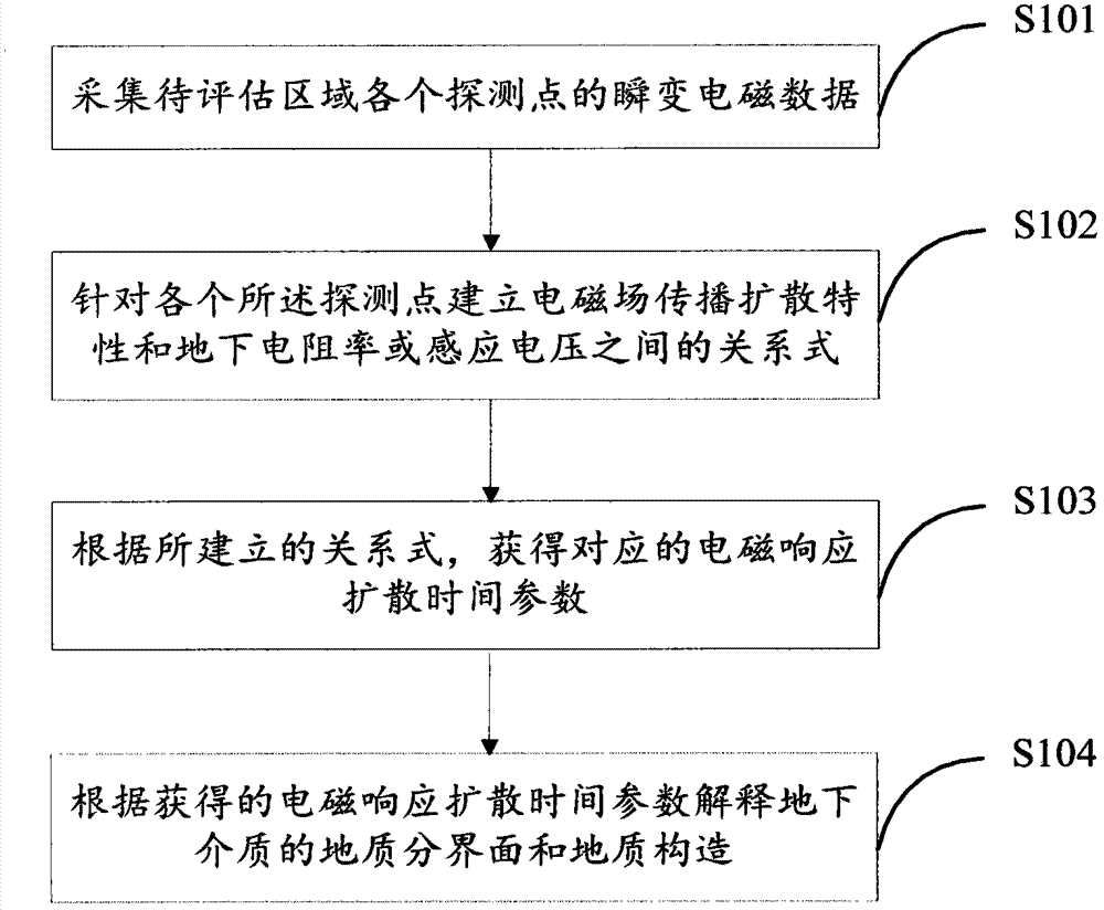
A geological structure and interface technology, applied in the direction of surveying devices, radio wave measurement systems, electric/magnetic exploration, etc., can solve problems such as difficulty in solution, difficulty in application, non-uniqueness, etc., and achieve improved resolution, effective resolution, The effect of improving reliability

Inactive Publication Date: 2015-07-01
INST OF GEOLOGY & GEOPHYSICS CHINESE ACAD OF SCI
View PDF3 Cites 5 Cited by
  • Summary
  • Abstract
  • Description
  • Claims
  • Application Information

AI Technical Summary

Problems solved by technology

Based on reflection coefficient quasi-seismic imaging technology, the equations of the solution are underdetermined equations, and the solution is non-unique; there is another method, which uses the wave field conversion method to realize the imaging of the interface by the transient electromagnetic method, but The wave field transformation equation is an ill-conditioned equation, which is difficult to solve and difficult to apply

Method used


Image

  • Geological interface structure detection method, device and system
  • Geological interface structure detection method, device and system
  • Geological interface structure detection method, device and system

Examples


Embodiment 1

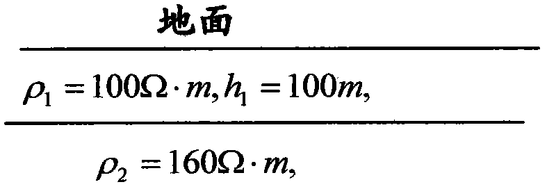
[0108] First design the geological model ( image 3 ), (where, ρ 1 =100Ω·m, h 1 = 100m, ρ 2 =160Ω·m), the sending current is 10A, the sending side is 100 meters long, the time channel is 20, and the time delay range is 0.087ms-7.ms (Table 1). Figure 4 To calculate the apparent resistivity curve for forward modeling, the abscissa is the time channel with equal logarithmic interval, and the ordinate is the apparent resistivity value.

[0109] Table 1 Each time channel and the corresponding diffusion time

[0110]

[0111] Figure 5 It is the curve graph of the new attenuation parameters calculated, the abscissa is still the time channel with equal logarithmic interval, and the ordinate is the differential parameter value of the infinite rigidity. From Figure 5 It can be seen that there is a sharp peak in the seventh time trace, which corresponds to the geological interface.

Embodiment 2

[0113] The method provided by the embodiment of the present invention is used to process the transient electromagnetic method detection data in a certain area, and the purpose is to better determine the underground geological structure and geological structure. Figure 6 It is the cross-sectional view of apparent resistivity under normal conditions. The abscissa in the figure indicates the position of the measuring point, and the ordinate indicates the exploration depth. The formula for calculating the exploration depth is as follows:

[0114] where μ 0 =4π×10 -7 h / m

[0115] when based on Figure 6 When making judgments on geological conditions, it largely depends on the work experience of professional and technical personnel, which is often prone to misjudgment. Figure 7It is a cross-sectional diagram of electromagnetic response diffusion time parameters made according to the embodiment of the present invention, and the diagram provides underground geological informa...


PUM


Abstract

The invention provides a geological interface structure detection method, device and system and relates to the fields of geology and geophysics, and the reliability and resolution of interface resolution interpretation through detection by the electromagnetic method can be improved. The method includes acquiring transient electromagnetic data of detection points of a region to be estimated; establishing a relational expression between the electromagnetic field diffusion characteristics and subsurface resistivity or induction voltage according to the detection points; according to the established relational expression, acquiring the corresponded electromagnetic response diffusion time parameters; according to the acquired electromagnetic response diffusion time parameters, interpreting the geological interface and geological structure of the subsurface medium. The reliability of interpretation of detection by the transient electromagnetic method is improved, the resolution of the method is improved, the geological interface and geological structure of the subsurface medium can be segmented directly and clearly, and the interface resolution can be performed rapidly and effectively.

Description

technical field [0001] The invention relates to the fields of geology and geophysics, in particular to a detection method, device and system for geological interface structures. Background technique [0002] Transient Electromagnetic Method (TEM, Transient Electromagnetic Method) is a common geophysical method based on electromagnetic induction, which can provide underground geoelectric information. In recent years, the theoretical and applied research work of using transient electromagnetic method to explore oil, geothermal sources and various mineral resources has been developing continuously. TEM has been proved to be an effective method for detecting low-resistance anomalies buried underground. However, due to the complexity of electromagnetic phenomena in layered, lossy media, the current level of interpretation of measured data is still low. [0003] The horizontal thin plate model is the only geoelectric model that can be analytically expressed by elementary function...

Claims


Application Information

Patent Timeline
Patent Type & Authority Applications(China)
IPC IPC(8): G01V3/38
Inventor 薛国强钟华森侯东洋马振军
Owner INST OF GEOLOGY & GEOPHYSICS CHINESE ACAD OF SCI
Learn More