A gas solenoid valve control circuit

A gas solenoid valve and control circuit technology, which is applied to battery circuit devices, circuit devices, valve devices, etc., can solve problems such as the malfunction of the control solenoid valve, the high energy consumption of the solenoid valve operation, and the poor anti-interference ability of the solenoid valve control circuit. , to achieve the effect of reducing the working current intensity, promoting the application value, and saving energy.

Active Publication Date: 2018-09-28
浙江汉特姆阀门有限公司
View PDF7 Cites 0 Cited by
  • Summary
  • Abstract
  • Description
  • Claims
  • Application Information

AI Technical Summary

Problems solved by technology

[0003] In the prior art, 1. When the control circuit of the solenoid valve is driving the solenoid coil of the solenoid valve, it needs a certain current to be able to control. The existing control circuit needs to have a large enough current to maintain , can ensure the normal operation of the solenoid valve, so the operation energy consumption of the solenoid valve is high in this case; 2. Due to the instantaneous voltage change of the power supply voltage sometimes, it will cause the malfunction of the control solenoid valve and affect the overall operation of the entire equipment. 3. The anti-interference ability of the solenoid valve control circuit is poor. When the external signal fails, the solenoid coil will continue to be energized, and the overload of the solenoid coil will easily cause a fire and form a safety hazard.

Method used


Image

  • A gas solenoid valve control circuit
  • A gas solenoid valve control circuit
  • A gas solenoid valve control circuit

Examples


Embodiment Construction

[0017] The specific embodiments of the present invention will be further described in detail below in conjunction with the accompanying drawings.

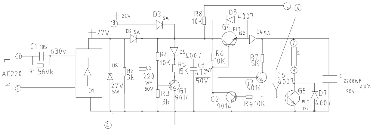
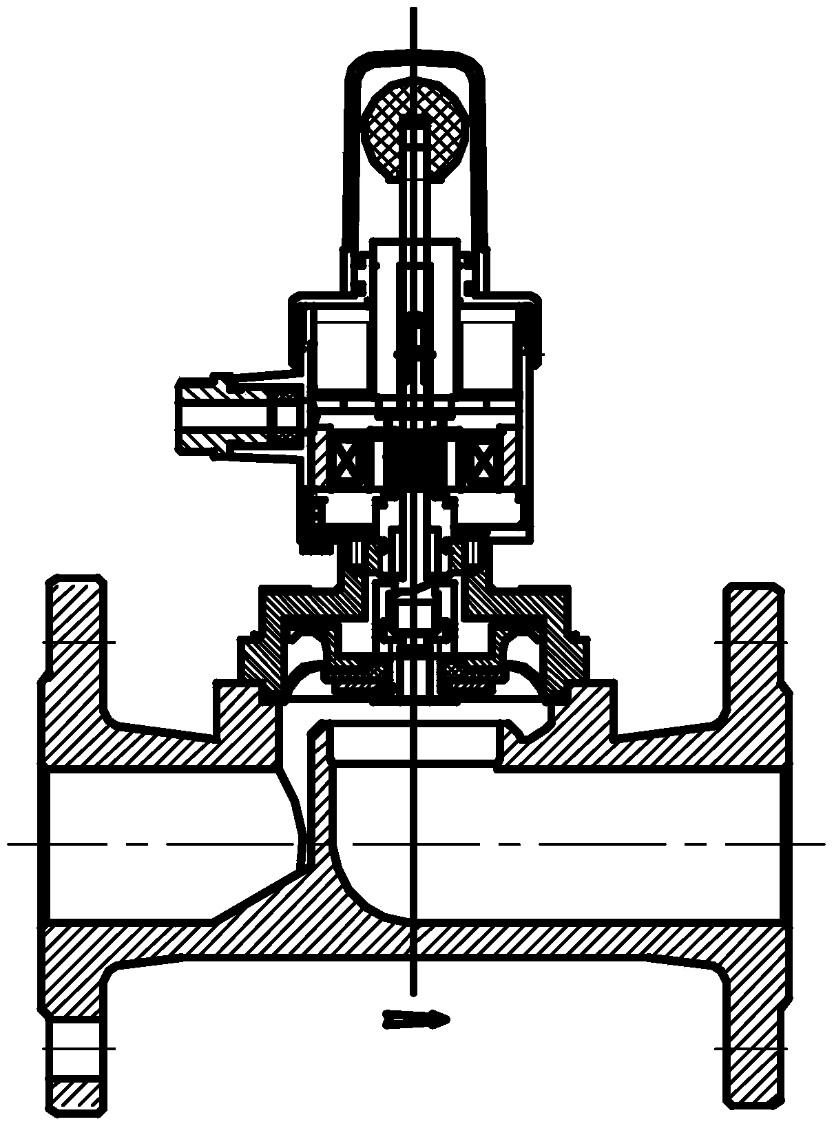
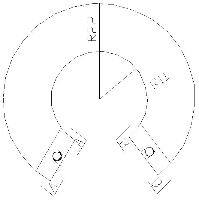
[0018] Such as figure 1 , 2 , 3, 4, 5, a gas solenoid valve control circuit, including: alternating current AC 200V, the first triode G1, the second triode G2, the third triode G3, the fourth triode G4 , the fifth triode G5; the first capacitor C1 and the capacitor C; the Schottky diode US, the first diode D1, the second diode D2, the third diode D3, the fourth diode D4, Fifth diode D5, sixth diode D6, seventh diode D7, eighth diode D8; first resistor R1, second resistor R2, third resistor R3, fourth resistor R4, fifth The resistor R5, the sixth resistor R6, and the seventh resistor R7, wherein, the AC 220V capacitor step-down full-wave rectification and voltage stabilization device composed of the first capacitor C1, the first diode D1, and the Schottky diode US, The alternating current AC220V passes through the first capacitor...


PUM


Abstract

The invention discloses a fuel gas electromagnetic valve control circuit. The fuel gas electromagnetic valve control circuit comprises an alternating current AC 220 V, a first triode G1, a second triode G2, a third triode G3, a fourth triode G4, a fifth triode G5, a first capacitor C1, a capacitor C, a Schottky diode US, a first diode D1, a second diode D2, a third diode D3, a fourth diode D4, a fifth diode D5, a sixth diode D6, a seventh diode D7, an eighth diode D8, a first resistor R1, a second resistor R2, a third resistor R3, a fourth resistor R4, a fifth resistor R5, a sixth resistor R6 and a seventh resistor R7. An alternating current AC 220 V capacitance voltage reduction full-wave rectification voltage stabilizing device is formed by the first capacitor C1, the first diode D1 and the Schottky diode US, an alternating current AC 220 V passes the first capacitor C1 and the first resistor R1, the alternating current with the reduced voltage enters the first diode D1, then the alternating current with reduced voltage finally enters the Schottky diode US, full-wave rectification is carried out through the Schottky diode US, the alternating current passes the second resistor R2, and a 27 V direct current power source power supply device is formed.

Description

technical field [0001] The invention relates to a control circuit of a solenoid valve, in particular to a control circuit of a gas solenoid valve which is manually opened and powered off. Background technique [0002] Solenoid valves for natural gas are the main equipment in gas transmission equipment. With the development of the national economy, they are widely used in production and living facilities. They are indispensable for control devices. , Reliability is more important. [0003] In the prior art, 1. When the control circuit of the solenoid valve is driving the solenoid coil of the solenoid valve, it needs a certain current to be able to control. The existing control circuit needs to have a large enough current to maintain , can ensure the normal operation of the solenoid valve, so the operation energy consumption of the solenoid valve is high in this case; 2. Due to the instantaneous voltage change of the power supply voltage sometimes, it will cause the malfuncti...

Claims


Application Information

Patent Timeline
Patent Type & Authority Patents(China)
IPC IPC(8): F16K31/06H02J7/34
CPCF16K31/0655F16K31/0675
Inventor 池玉夫叶东军
Owner 浙江汉特姆阀门有限公司
Why Eureka
Try Eureka