
Hybrid electric system adopting double-rotor motor and implementation method of hybrid electric system adopting double-rotor motor

A technology of hybrid power system and dual-rotor motor, which is applied in the field of power system, can solve the problems of poor power output of lithium battery and poor engine smoothness, and achieve the effects of good low-speed climbing ability, smooth start at low temperature, and high work efficiency

Active Publication Date: 2015-07-01
UNITED AUTOMOTIVE ELECTRONICS SYST
View PDF7 Cites 11 Cited by
  • Summary
  • Abstract
  • Description
  • Claims
  • Application Information

AI Technical Summary

Problems solved by technology

Due to the chemical characteristics of lithium battery materials at low temperatures, the power output of lithium batteries is poor, which makes the smoothness of engine cold start at low temperature poor

Method used


Image

  • Hybrid electric system adopting double-rotor motor and implementation method of hybrid electric system adopting double-rotor motor
  • Hybrid electric system adopting double-rotor motor and implementation method of hybrid electric system adopting double-rotor motor
  • Hybrid electric system adopting double-rotor motor and implementation method of hybrid electric system adopting double-rotor motor

Examples


Embodiment Construction

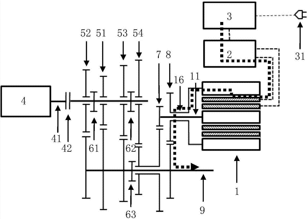
[0031] see figure 1 , the dual-rotor motor used in this application includes:

[0032] ——The housing 10 surrounds the remaining components, wherein the output shaft 11 of the inner rotor motor and the output shaft 16 of the outer rotor motor extend out of the housing 10 .

[0033] ——The output shaft 11 of the inner rotor motor is sealed with the casing 10 by bearing one 101 .

[0034] ——The inner rotor 12 surrounds and is fixed on the inner rotor motor shaft 11, and the two keep rotating synchronously.

[0035] - The inner stator 13 surrounds the inner rotor 12 with a gap in between.

[0036] - the outer stator 14 surrounding the inner stator 13 . The inner stator 13 and the outer stator 14 share a stator bracket and are fixed to the casing 10 by fixing bolts 135 . There is a cooling water channel 145 between the inner stator 13 and the outer stator 14 .

[0037] - The outer rotor 15 surrounds the outer stator 14 with a gap in between. An outer rotor position sensor 155,...


PUM


Abstract

The invention discloses a hybrid electric system adopting a double-rotor motor. The hybrid electric system comprises the double-rotor motor, a double-motor controller and an engine, wherein the double-rotor motor comprises an inner rotor motor and an outer rotor motor; the inner rotor motor is engaged with a power output shaft or a four-speed gear bank through an inner rotor motor reduction gear bank; the outer rotor motor is connected with the power output shaft through an outer rotor motor reduction gear bank; the double-motor controller is used for independently controlling the inner rotor motor and the outer rotor motor, and is connected with a power battery; an output shaft of the engine is engaged with one of a one-speed gear bank, a two-speed gear bank, a three-speed gear bank and the four-speed gear bank through a clutch, or not engaged with the one-speed gear bank, the two-speed gear bank, the three-speed gear bank and the four-speed gear bank; the one-speed gear bank, the two-speed gear bank and the three-speed gear bank are connected with the power output shaft; the four-speed gear bank is engaged with the power output shaft or the inner rotor motor reduction gear bank. The hybrid electric system adopting the double-rotor motor and an implementation method of the hybrid electric system adopting the double-rotor motor have the characteristics of compact structure, high integration of the system, high efficiency of the vehicle, good fuel economy, smoothness in low-temperature coldstart of the engine and good grade ability at a low speed.

Description

technical field [0001] The present application relates to a power system of a hybrid electric vehicle. Background technique [0002] A hybrid vehicle is a vehicle that uses more than two sources of energy. The most common hybrid electric vehicle (HEV for short) has an engine and an electric motor, the engine consumes fuel, and the electric motor consumes electric energy of the power battery. [0003] HEV mainly has three types of hybrid systems: Series Hybrid, Parallel Hybrid and Combined Hybrid or Series-Parallel Hybrid or Parallel-Series Hybrid. [0004] The series hybrid system only uses the electric motor as the driving device, and the engine is only used as a generator to charge the power battery and supply power to the electric motor. Since the engine does not directly participate in the driving of the vehicle and is limited by the power of the electric motor, the dynamic performance of the vehicle is generally poor. [0005] A parallel hybrid system uses the engine...

Claims


Application Information

Patent Timeline
IPC IPC(8): B60K6/26B60K6/36B60K6/44
CPCY02T10/62
Inventor 顾佳鼎李至浩王萑
Owner UNITED AUTOMOTIVE ELECTRONICS SYST
Learn More