Massage apparatus

A rotary drive, liquid tank technology, applied in bathing devices, hydraulic massage, vibration massage, etc., can solve problems such as deterioration of assembly operability, increase in the number of parts, and burning of motors, etc., to improve assembly operability, reduce the number of parts, Achieving the effect of cost reduction

Inactive Publication Date: 2015-06-24
OG GIKEN CO LTD
View PDF3 Cites 0 Cited by
  • Summary
  • Abstract
  • Description
  • Claims
  • Application Information

AI Technical Summary

Problems solved by technology

[0006] The existing massage device has the following problems: Since the two ends of the threaded shaft are rotatably fixed and supported on the bearing unit, the requirements for the size of the threaded shaft and the processing of the end of the threaded shaft inserted into the bearing unit are relatively high. If the centering accuracy of the threaded shaft is poor, the threaded shaft cannot rotate properly, which will cause trouble for the smooth running of the trolley or the power of the rotating motor cannot be reliably transmitted to the worm wheel. As a result, the rotation of the gear bring bad influence
[0007] In addition, there is a problem that if the moving motor or the turning motor is continuously driven in a state where the centering accuracy is poor, a load exceeding a specified value is applied to the motor, which may cause motor failure such as burnout.
[0008] Furthermore, during the assembly operation in the manufacturing factory of the massage device, the centering adjustment operation of the threaded shaft takes a long time, and this operation becomes one of the main factors that deteriorate the assembly workability of the massage device, and the assembly workability needs to be improved.
[0009] In addition, there is also the following problem: for the screw shaft used to rotate the injection port moving mechanism in the short side direction, when the rotation motor is driven, in order to reduce the stress imposed on the one end side of the screw shaft and the rotation motor. For the thrust load of the bearing unit on one side, the end face of the other end side of the threaded shaft is pressed toward the direction of the rotation motor by using the end block made of resin, but this will increase the number of parts and become a major cause of cost increase. , and the end block wears due to friction caused by the rotation of the threaded shaft so that the pressing force gradually decreases

Method used


Image

  • Massage apparatus
  • Massage apparatus
  • Massage apparatus

Examples


Embodiment Construction

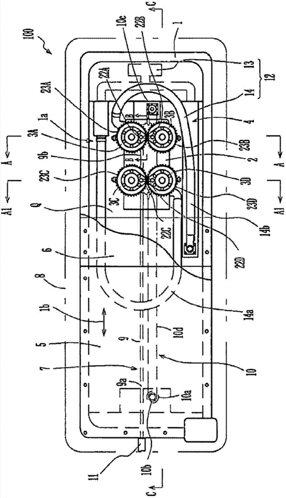
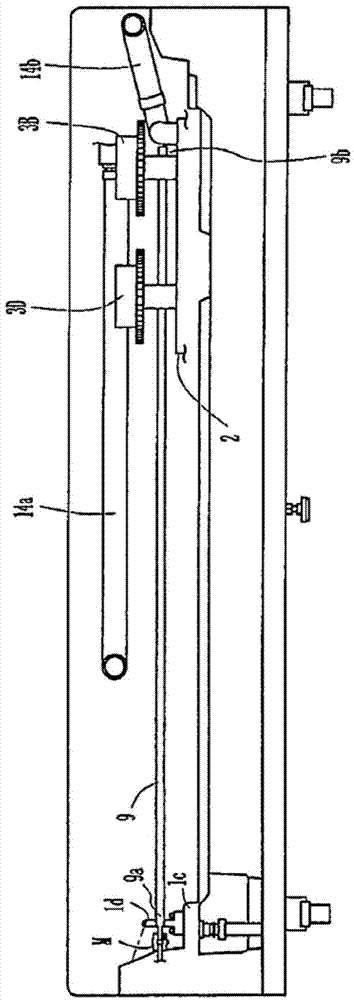
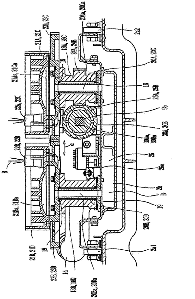
[0029] Next, a massage device according to an embodiment of the present invention will be described with reference to the attached drawings. figure 1 It is a schematic plan view of the massage device according to the embodiment of the present invention. figure 2 is along figure 1 A cross-sectional view of line C-C. image 3 is along figure 1 Partial sectional view of line A-A. Additionally, along the figure 1 The partial cross-sectional view of line A1-A1 is also with image 3 same. Figure 4 It is a partial sectional view of one end side of the shaft. Figure 5 is along figure 1 Partial sectional view of line B-B. Image 6 Yes Figure 5 An enlarged view of the main part. Figure 7 It is a schematic diagram of the structure used to switch the injection part.

[0030] The massage device 100 includes a liquid tank 1 , a moving trolley 2 , first to fourth jetting units 3A to 3D, a jetting liquid supply unit 4 , a flexible sheet 5 , a flexible reinforcing belt 6 , a tr...


PUM


Abstract

[Problem] To reduce the time required for centering work and improve assembly work efficiency for a massage device when supporting a shaft that moves a jet part having a jet nozzle, and to reduce costs without hindering movement of the jet nozzle. [Solution] This massage apparatus comprises: a rotary drive part (11); a shaft (9), one end (9a) of which is rotatably connected to the rotary drive part (11) and is supported by a bearing (27), and the other end (9b) of which extends in one direction inside a liquid tank (1); threaded gears (25A, 25B) disposed on the shaft (9); a jet part that is able to move along the shaft (9) with the threaded gears (25A, 25B), has a jet nozzle at the top, and can be rotated by the rotation of the threaded gears (25A, 25B); and a support mechanism that supports the other end (9b) of the shaft (9) in a non-fixed state.

Description

technical field [0001] The invention relates to a massage device which uses jet hydraulic pressure to massage the neck, trunk and lower limbs of a human body lying on its back. Background technique [0002] Conventionally, as a massage device for massaging a human body, a massage device utilizing hydraulic pressure such as water pressure jetted from a jet port (jet nozzle) is known. This massage device is a device as follows (for example, refer to Patent Document 1): a flexible sheet is tensioned above the upper opening of a substantially rectangular parallelepiped liquid tank, and the flexible sheet is directed toward the flexible sheet from an injection port arranged in the liquid tank. The lower surface of the flexible sheet ejects jet liquid, thereby giving stimulation to a massage subject lying on the flexible sheet for treatment. [0003] The massage device is provided with jet port moving mechanisms for moving the jet ports in the longitudinal direction and the short...

Claims


Application Information

Patent Timeline
Patent Type & Authority Applications(China)
IPC IPC(8): A61H9/00A61H23/04A61H33/00
CPCA61H9/0021A61H33/6005A61H33/6021A61H2201/1215A61H2201/1454A61H2201/1463A61H2201/149A61H2201/1654A61H2201/1666A61H2201/1669
Inventor 伊藤伸一正子洋二
Owner OG GIKEN CO LTD
Why Eureka
Try Eureka