Multifunctional numerically-controlled rear material stopping device

A backgauge and multi-functional technology, which is applied in the field of sheet metal bending, can solve the problems of out-of-sync on both sides of the backgauge and easy material deviation, etc., and achieve the effect of reducing transmission gap, low cost, and eliminating gaps

Active Publication Date: 2015-06-24
JIANGSU YAOU CNC MACHINE
View PDF8 Cites 5 Cited by
  • Summary
  • Abstract
  • Description
  • Claims
  • Application Information

AI Technical Summary

Problems solved by technology

[0006] Purpose of the invention: In order to solve the deficiencies of the prior art, the present invention provides a numerically controlled multifunctional backgauge device, which ensures the precise positioning of the backgauge of the bending machine, solves the problem of asynchrony between the two sides of the backgauge and the alignment of the material during bending The problem of easy deviation

Method used


Image

  • Multifunctional numerically-controlled rear material stopping device
  • Multifunctional numerically-controlled rear material stopping device
  • Multifunctional numerically-controlled rear material stopping device

Examples


Embodiment

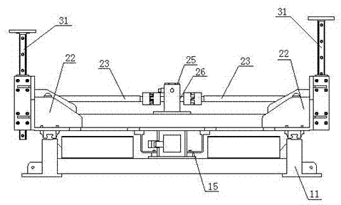
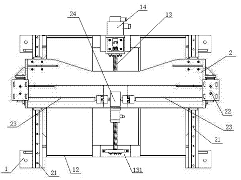
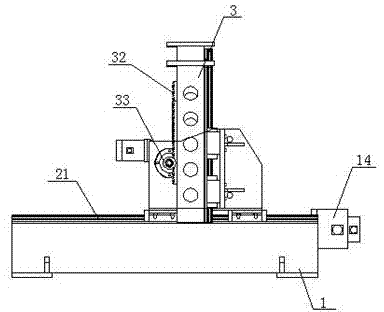
[0029] Such as Figure 1-4 As shown, a numerically controlled multifunctional backgauge device includes an X-axis backgauge 1, an R-axis backgauge 2 installed on the X-axis backgauge, and a Y axis fixedly installed above the R-axis backgauge. Shaft back gauge 3.

[0030] The X-axis backgauge 1 includes a support base 11, a linear guide pair 12 with a slider 121 arranged on the support base 11, an X-axis ball screw 13 fixed by a screw bearing seat 131, and an X-axis ball screw 13 fixed on the X-axis. The servo motor 14 on the ball screw 13, the slider 121 and the X-axis ball screw 13 are fixedly connected through the screw base connecting bracket 15; the screw base connecting bracket 15 is a U-shaped bracket.

[0031] The R-axis backgauge 2 includes a sliding guide rail 21 fixed on the support base 11, an R-axis bearing seat 22 installed on the sliding guide rail 21, and 2 mounted on the same straight line on the R-axis bearing seat 22. A R-axis gear shaft 23 and a servo moto...


PUM


Abstract

The invention discloses a multifunctional numerically-controlled rear material stopping device which comprises an X-axis rear material stopping device body, an R-axis rear material stopping device body and a Y-axis rear material stopping device body. The X-axis rear material stopping device body comprises a supporting base, a linear guide rail pair, an X-axis ball screw and a servo motor arranged on the X-axis ball screw. The R-axis rear material stopping device body comprises a sliding guide rail fixed to the supporting base, an R-axis bearing seat arranged on the sliding guide rail, two R-axis gear shafts arranged on the R-axis bearing seat and located on the same straight line, and a servo motor arranged between the two R-axis gear shafts. The Y-axis rear material stopping device body comprises a crossbeam lifting stand column fixed to the R-axis bearing seat, a rack arranged on the crossbeam lifting stand column, and a speed reduction mechanism arranged in the crossbeam lifting stand column. The multifunctional numerically-controlled material stopping device has the advantages of being high in precision and speed, low in noise, attractive in appearance, convenient to install, easy to operate, high in safety and the like.

Description

technical field [0001] The invention belongs to the field of sheet metal bending, and in particular relates to a numerically controlled multifunctional rear stopper, which is used for precision control of the stopper of a sheet metal bending machine in the forging industry. Background technique [0002] The traditional backgauge is split and installed on both sides of the machine tool, and the motor drives the chain to drive. When installing, the ball wires on both sides and the parallelism of the rod linear guide rail up and down, left and right cannot be guaranteed, so the speed cannot be too fast, and the noise will be too fast. If the chain is used for a long time, it will stretch or break, causing the two sides to be out of sync, and the positioning accuracy and normal use of the stopper cannot be guaranteed. [0003] The traditional back gauge beam cannot be raised and lowered, and the shelf cannot be lowered on the lower mold of the bending machine, so there is a gap ...

Claims


Application Information

Patent Timeline
Patent Type & Authority Applications(China)
IPC IPC(8): B21D5/00
CPCB21D5/002
Inventor 李忠军
Owner JIANGSU YAOU CNC MACHINE
Why Eureka
Try Eureka