Ion exchange membrane electrolytic cell

An ion exchange membrane and electrolytic cell technology, which is applied in the electrolysis process, electrolysis components, diaphragms, etc., can solve the problems of thin wire penetration, plastic deformation of damaged ion exchange membrane, uneven distance between electrodes, etc.

Inactive Publication Date: 2015-06-17
CHLORINE ENGINEERS CORP LTD
View PDF2 Cites 1 Cited by
  • Summary
  • Abstract
  • Description
  • Claims
  • Application Information

AI Technical Summary

Problems solved by technology

[0004] However, conventional non-rigid materials have the disadvantage that when the non-rigid material is excessively pressed from the anode side after the non-rigid material is installed in the electrolytic cell, the non-rigid material is locally deformed so that the distance between the electrodes becomes smaller. Thin threads of non-uniform or non-rigid material penetrate the ion exchange membrane
In addition, rigid materials such as leaf springs have the disadvantage of damaging the ion exchange membrane or causing plastic deformation so that they cannot be reused.

Method used


Image

  • Ion exchange membrane electrolytic cell
  • Ion exchange membrane electrolytic cell
  • Ion exchange membrane electrolytic cell

Examples


Embodiment 1

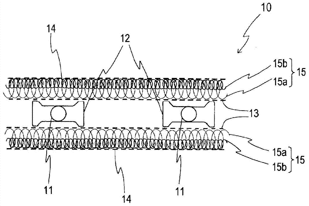
[0053] A dimensionally stable electrode manufactured by Japan Permanent Electrode Co., Ltd. was used as the anode, and an active cathode with a nickel microporous mesh substrate was used as the cathode. The dimensions of the reaction surfaces of the anode and the cathode were respectively set to a width of 110 mm and a height of 1400 mm. As the ion exchange membrane, Flemion F-8020 manufactured by Asahi Glass Co., Ltd. was used.

[0054] Furthermore, the wire diameter is 0.17mm and the tensile strength is 620N / m by rolling processing. 2 ~680N / m 2 The nickel wire (NW2201) is made into a coil wire with a width of about 0.5mm. Using the obtained coil wire, a metal coil with a winding diameter of 6.5 mm was produced as a metal coil body with a small reaction force, and a metal coil body with a coil winding diameter of 4.5 mm was produced as a relative Metal coil body with high reaction force. The reaction force ratio of the obtained metal coil body was 0.7. This metal coil bo...

Embodiment 2

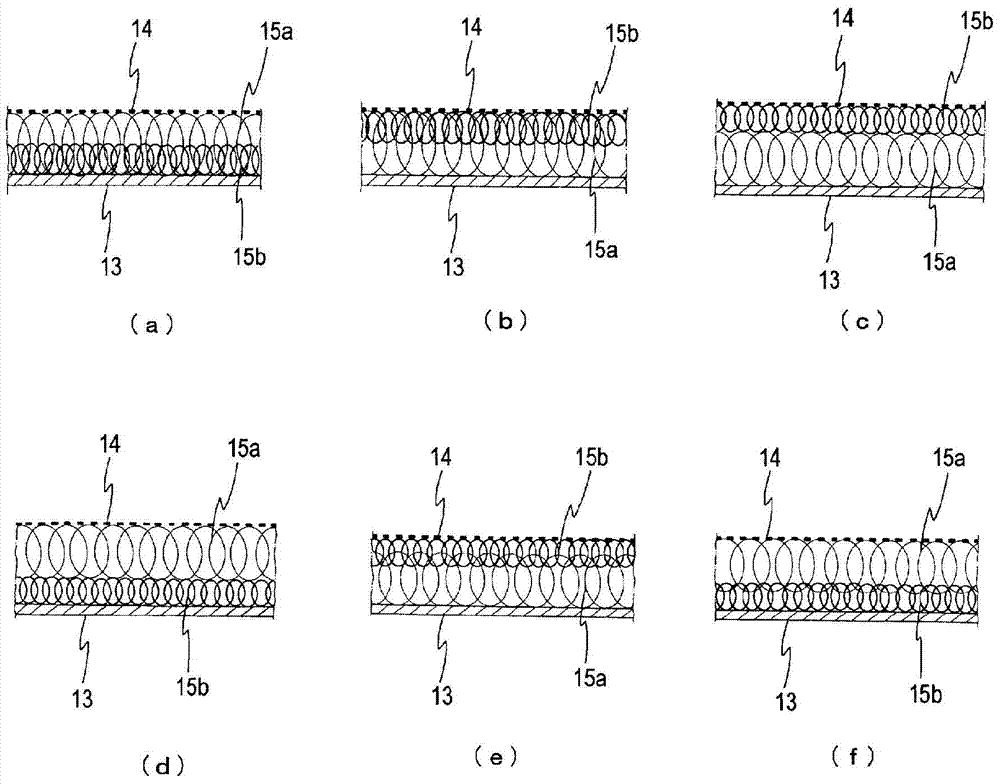
[0057] Instead of winding a metal coil body with a large diameter and a metal coil body with a small diameter around a corrosion-resistant frame, the metal coil body with a large diameter and a metal coil with a small diameter Electrolysis was performed under the same conditions as in Example 1 except that a body was inserted between the cathode current collector and the hydrogen generating cathode. In addition, the above-mentioned metal coil body is formed figure 2 The state shown in (a).

Embodiment 3

[0059] With the elastic buffer material made in Example 1 as the negative electrode, utilize the brush plating method (current 0.5A, every Plated 1dm 2 5 minutes), the ion-exchange membrane side surface of each metal coil body constituting the elastic cushioning material was plated with platinum. Electrolysis was performed under the same conditions as in Example 1, except that the obtained platinum-plated elastic buffer itself was used as a cathode and inserted between the cathode current collector and the ion-exchange membrane.


PUM

PropertyMeasurementUnit
Wire diameteraaaaaaaaaa

Abstract

Provided is an ion exchange membrane electrolytic cell, whereby it becomes possible to achieve both the protection of an ion exchange membrane and the development of the electrolytic performance of the electrolytic cell. An ion exchange membrane electrolytic cell partitioned with an ion exchange membrane into an anode chamber in which an anode is housed and a cathode chamber in which a hydrogen-generating cathode is housed, wherein a metallic elastic body (15) or an elastic cushioning material produced by winding a metallic elastic body around a corrosion-resistant frame is arranged between the hydrogen-generating cathode (14) and a cathode current collector (13) and / or between the anode and an anode current collector, and wherein at least two types of metallic elastic bodies are used as the metallic elastic body (15).

Description

technical field [0001] The present invention relates to an ion-exchange membrane electrolyzer (hereinafter also referred to as "electrolyzer"), in detail, relates to an ion-exchange membrane electrolyzer capable of taking into account the protection of the ion-exchange membrane and the electrolysis performance of the electrolyzer. Background technique [0002] In an ion-exchange membrane electrolyzer used for chlor-alkali electrolysis, the anode, the ion-exchange membrane, and the hydrogen-generating cathode are generally arranged in close contact with each other to reduce the electrolysis voltage. However, in a large electrolytic cell with an electrolysis area of ​​even several square meters, when the anode and cathode of the rigid member are accommodated in the electrode chamber, it is difficult to make the two electrodes closely adhere to the ion exchange membrane and to reduce the distance between the electrodes. Keep at the specified value. [0003] Electrolytic cells ...

Claims


Application Information

Patent Timeline
IPC IPC(8): C25B13/02C25B9/00C25B13/04
CPCC25B1/02C25B9/19
Inventor 浅海清人
Owner CHLORINE ENGINEERS CORP LTD
Why Eureka
Try Eureka