
Cylinder face photometric measurement device

A technology of photometric measurement and cylindrical surface, which is applied in the field of cylindrical photometric measurement devices, can solve the problems of high manufacturing cost of parabolic reflectors, harsh measurement environment requirements, and difficulty in popularization and use, and achieve low cost, simple and low equipment, and high precision Effect

Active Publication Date: 2015-06-17
UNIV OF SCI & TECH BEIJING
View PDF6 Cites 2 Cited by
  • Summary
  • Abstract
  • Description
  • Claims
  • Application Information

AI Technical Summary

Problems solved by technology

However, due to the light passing through multiple lenses and parabolic mirrors during the propagation process, the catadioptric characteristics of the lens / mirror itself are superimposed on the measured material, which interferes with the measurement results
In addition, the manufacturing cost of the parabolic reflector is relatively high, and the measurement environment is demanding, so it is not easy to popularize and use

Method used


Image

  • Cylinder face photometric measurement device
  • Cylinder face photometric measurement device
  • Cylinder face photometric measurement device

Examples


Embodiment 1

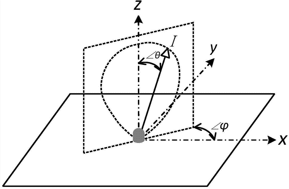
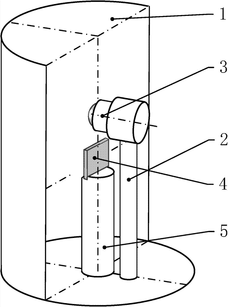
[0058] Such as image 3 As shown, the cylindrical light screen 1 is a cylindrical surface with an arc-shaped cross section, and the radius of the cylindrical surface is R; the stage 4 is located at the midpoint of the axis of the cylindrical light screen 1, which is recorded as the sample point S; The center C is located on the midpoint of the axis of the cylindrical light screen 1 and the distance from the sample point S is d, and the optical axis of the camera is perpendicular to the cylindrical axis and faces the light screen. Taking the sample point S as the coordinate origin, establish as Figure 4 The world coordinate system S shown xyz -(x,y,z), while establishing a sample spherical coordinate system S ρ -(ρ,,). The position of the optical center C of the fisheye camera 3 in the world coordinate system is S xyz -(0,0,d), with point C as the origin, establish the camera ball coordinate system C rαβ -(r,α,β). Based on the center point P of the captured photo, an ima...

Embodiment 2

[0074] Such as Figure 5 As shown, the optical screen 1 is a cylindrical surface with a circular cross-section, and the radius of the cylindrical surface is R; the stage 4 is located at the midpoint of the axis of the cylindrical optical screen 1, which is recorded as the sample point S; The distance between the midpoint of the axis of the cylindrical light screen 1 and the sample point S is d, and the optical axis of the camera coincides with the axis of the cylindrical light screen 1 . Taking the sample point S as the coordinate origin, establish as Figure 4 The world coordinate system S shown xyz -(x,y,z), while establishing a sample spherical coordinate system S ρ -(ρ,,). The position of fisheye camera 3 optical center C in the world coordinate system is S xyz -(0,0,d), with point C as the origin, establish the camera ball coordinate system C rαβ -(r,α,β). Based on the center point P of the captured photo, an image coordinate system P is established uv -(u,v), the ...


PUM


Abstract

The invention belongs to the field of photometric measurement and relates to a cylinder face photometric measurement device used for measuring the distribution rule of the emergence light intensity and the emergence light angle of a light source or a refraction and reflection material. Emergence light in all directions in space is collected through the inner wall of a cylinder face light screen, and the emergence light intensity reflects the irradiated brightness of the cylinder face light screen. The brightness irradiated by the emergence light of the inner wall of the cylinder face light screen is measured through a fisheye camera, the angle corresponding to the emergence light is obtained through image coordinates according to the fisheye camera coordinate conversion relation, and therefore the distribution rule of emergence light intensity and the emergence light angle is established. Compared with a traditional method, emergence light intensity data within the emergence light angle in the 180-degree semispherical range can be measured at the same time, the data volume obtained through one-time measurement is large, efficiency is high, and the interference from the environment is low. Meanwhile, the measurement device has the advantages of being simple and easy to machine and low in cost.

Description

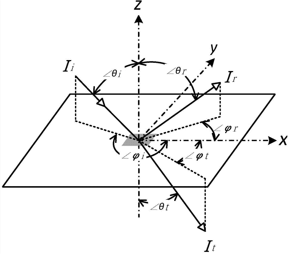
technical field [0001] The invention relates to a cylindrical photometric measuring device. It belongs to the field of optical measurement and is used to measure the distribution law between the intensity of light emitted by a light source or a catadioptric material and the angle of the light emitted. Background technique [0002] Photometry is a metrology subject that measures the intensity of light and its directionality of propagation. An important subject is to measure the distribution of light intensity in all directions in space. When the measurement object is a luminous light source, such as LED lamp beads, the measurement result is called the Luminous intensity distribution curve (LIDC), which is a function of the light intensity with respect to the angle of light emission. When the measurement object is a refraction / reflection material, the measurement result is called - bidirectional scattering distribution function (Bidirectional scattering distribution function,...

Claims


Application Information

Patent Timeline
Patent Type & Authority Applications(China)
IPC IPC(8): G01J1/00
Inventor 徐科王磊
Owner UNIV OF SCI & TECH BEIJING
Learn More