
Novel jig dying machine shell with heating device

A technology for heating devices and jiggers, which is applied to textile processing machine accessories, textile material processing, and textile material processing equipment configuration. The effect of simple and convenient disassembly, uniform and stable heating, and reduced manual labor

Active Publication Date: 2015-06-17
汪建建
View PDF4 Cites 2 Cited by
  • Summary
  • Abstract
  • Description
  • Claims
  • Application Information

AI Technical Summary

Problems solved by technology

[0002] Fabrics of different colors are dyed by printing and dyeing machines, and jiggers are used more often. In order to ensure the dyeing effect, the dyeing liquid needs to be kept at a certain temperature. The existing heating method The steam heating tube is used for heating, and when the steam is insufficient, the dyeing liquid cannot be heated, so that the dyeing cannot be done normally, and the normal operation of the steam pipeline is affected by many components. It will affect the normal supply of steam, thereby affecting the normal operation of the dyeing machine
[0003] Moreover, the cover of the existing printing and dyeing machine is generally opened manually, which is troublesome to open, increases the amount of manual labor, and has poor sealing effect.
[0004] Moreover, the cloth reel of the existing winding machine is fixed on the rotating shaft by clamping the two ends of the cloth reel shaft to the rotating plates on both sides, and fixing it by means of bolts, etc. very troublesome

Method used


Image

  • Novel jig dying machine shell with heating device
  • Novel jig dying machine shell with heating device
  • Novel jig dying machine shell with heating device

Examples


Embodiment Construction

[0021] The present invention will be described in detail below in conjunction with accompanying drawings and specific preferred embodiments, so that the advantages and features of the present invention can be more easily understood by those skilled in the art. range is limited.

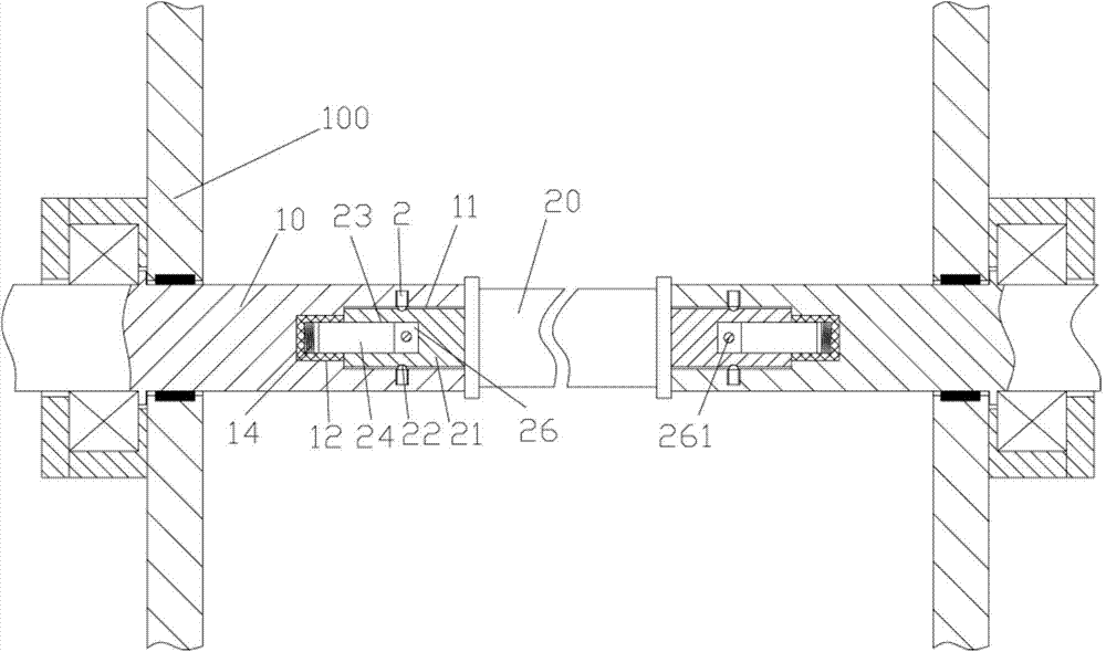
[0022] Examples, see e.g. Figure 1 to Figure 5 As shown, a novel jigger housing with a heating device includes a housing 100, a housing cover 101 is hinged on the outer wall of the housing 100, and the middle part of the housing cover 101 has a cover body protrusion extending downward. 102, the raised portion 102 of the cover body is inserted into the rubber sealing sleeve 103 and fixed on the rubber sealing sleeve 103, the outer wall of the rubber sealing sleeve 103 elastically presses against the top inner wall of the housing 100, and the bottom of the housing 100 There are two connecting water pipes 106 connected on both sides, and a push cylinder 107 is hinged on the left and right side walls of...


PUM


Abstract

The invention discloses a novel jig drying machine shell with a heating device. The novel jig drying machine shell comprises a shell, wherein the outer wall of the shell is hinged with a shell cover; the middle of the shell cover is provided with a cover body bulged part extending downwards; the cover body bulged part sleeves a rubber seal sleeve internally in an insertion mode, and is fixed on the rubber seal sleeve; the outer side wall of the rubber seal sleeve elastically presses the inner side wall of the top of the shell; two sides of the bottom of the shell are connected with two connecting water pipes in a communicated mode; the left and right side walls of the shell are hinged with pushing air cylinders; pushing rods of the pushing air cylinders are hinged to the bottom edges of at left and right sides of the shell cover; the heating device is fixed on the inner wall of the bottom of the shell; two side walls of the shell are hinged with rotation shafts; one end surfaces, extend into the shell, of the rotation shafts are provided with insertion grooves; bottom ends of the insertion grooves are provided with extension holes. The pushing air cylinders are adopted for opening the shell cover automatically so as to reduce the labor of workers; meanwhile, an electric heat wire type heating coil pipe is used for heating, is only affected by a power supply, and can be used for simply, conveniently and rapidly to mount and dismount of a fabric reel shaft.

Description

Technical field: [0001] The invention relates to the technical field of textile printing and dyeing equipment, and more specifically relates to a novel jigger casing with a heating device. Background technique: [0002] Fabrics of different colors are dyed by printing and dyeing machines, and jiggers are used more often. In order to ensure the dyeing effect, the dyeing liquid needs to be kept at a certain temperature. The existing heating method The steam heating tube is used for heating, and when the steam is insufficient, the dyeing liquid cannot be heated, so that the dyeing cannot be done normally, and the normal operation of the steam pipeline is affected by many components. It will affect the normal supply of steam, thereby affecting the normal operation of the dyeing jigger. [0003] Moreover, the cover of the existing printing and dyeing machine is generally opened manually, which is troublesome to open, increases the amount of manual labor, and has poor sealing eff...

Claims


Application Information

Patent Timeline
Patent Type & Authority Applications(China)
IPC IPC(8): D06B23/00D06B23/22D06B3/32
Inventor 徐强
Owner 汪建建
Learn More