Paying-off method of paying-off device

A technology of pay-off device and pay-off shaft, which is applied in the direction of conveying filamentous materials, thin material processing, transportation and packaging, etc., which can solve the problems of inconvenient operation, shortened service life of pay-off device, and inconvenient winding of coils, etc.

Active Publication Date: 2015-06-17
WUHU HANGTIAN SPECIAL CABLE FACTORY
View PDF5 Cites 3 Cited by
  • Summary
  • Abstract
  • Description
  • Claims
  • Application Information

AI Technical Summary

Problems solved by technology

[0002] At present, wire pay-offs are widely used in all walks of life, especially wire pay-offs for cables. It is inconvenient to release the coil. Occasionally, the support seat and the pay-off shaft must be separated to allow the coil to be placed on the pay-off shaft. This is inconvenient during operation, and frequent disassembly will wear the pay-off , shorten the service life of the pay-off device

Method used


Image

  • Paying-off method of paying-off device

Examples


Embodiment Construction

[0020] Specific embodiments of the present invention will be described in detail below in conjunction with the accompanying drawings. It should be understood that the specific embodiments described here are only used to illustrate and explain the present invention, and are not intended to limit the present invention.

[0021] In the present invention, in the absence of a contrary statement, the orientation words included in the term such as "up, down, left, right, inside, outside" only represent the orientation of the term in the normal use state, or for the purpose of A common term understood by those skilled in the art, and should not be considered as a limitation of the term.

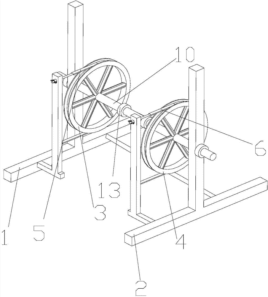
[0022] The invention provides a method for unwinding a wire payoff, such as figure 1 As shown, the structure of this pay-off device is such that the pay-off device includes a first support base 1, a second support base 2, a first runner 3, a second runner 4, a pay-off shaft 10, an installation The ...


PUM


Abstract

The invention discloses a paying-off method of a paying-off device. The paying-off device comprises a first supporting seat, a second supporting seat, a first rotary wheel, a second rotary wheel, a paying-off shaft, a first speed limiting part installed on the first rotary wheel, and a second speed limiting part installed on the second rotary wheel. One end of the paying-off shaft penetrates through the first rotary wheel and the first supporting seat, the other end of the paying-off shaft penetrates through the second rotary wheel and the second supporting seat, the two ends of the first speed limiting part are fixedly connected to the first supporting seat, the periphery of the first rotary wheel is sleeved with the first speed limiting part, the two ends of the second speed limiting part are fixedly connected to the second supporting seat, and the periphery of the second rotary wheel is sleeved with the second speed limiting part. The paying-off shaft comprises multiple sequentially-connected connecting sections, and every two adjacent connecting sections are connected through a detachable connecting mechanism. The paying-off method includes the steps that the paying-off shaft is split into the sequentially-connected connecting sections, the paying-off shaft is sleeved with a coil connected with the detachable connecting mechanisms, and the first speed limiting part and the second speed limiting part are adjusted. By the adoption of the paying-off method, paying-off operation of the paying-off device can be facilitated, and the abrasion degree of the paying-off device is reduced.

Description

technical field [0001] The present invention relates to a wire payoff, in particular to a wire payoff method for the wire payoff. Background technique [0002] At present, wire pay-offs are widely used in all walks of life, especially wire pay-offs for cables. It is inconvenient to release the coil. Occasionally, the support seat and the pay-off shaft must be separated to allow the coil to be placed on the pay-off shaft. This is inconvenient during operation, and frequent disassembly will wear the pay-off , shorten the service life of the pay-off device. [0003] Therefore, it is an urgent problem to be solved in the present invention to provide a method for a wire pay-off device that can facilitate the insertion of coils. Contents of the invention [0004] The purpose of the present invention is to provide a kind of pay-off method that can facilitate the pay-off of the wire pay-off, and the degree of wear of the pay-off can be slowed down by adopting the pay-off method....

Claims


Application Information

Patent Timeline
IPC IPC(8): B65H49/32B65H59/38
Inventor 何成龙杨趁芬何源佘晨
Owner WUHU HANGTIAN SPECIAL CABLE FACTORY
Why Eureka
Try Eureka