Eureka AIR delivers breakthrough ideas for toughest innovation challenges, trusted by R&D personnel around the world.

Selective compliance assembly robot

A technology of horizontal multi-joint, mechanical arm, applied in the direction of manipulator, program-controlled manipulator, mechanical equipment, etc., can solve the problems of reducing the accuracy of shaft position control, unstable transmission effect, and difficult to replace parts, etc.

Inactive Publication Date: 2015-06-17
HIWIN TECH
View PDF6 Cites 3 Cited by
  • Summary
  • Abstract
  • Description
  • Claims
  • Application Information

AI Technical Summary

Problems solved by technology

[0004] However, the aforementioned shaft driving device adopts an indirect driving method, so the efficiency is low, and the belt cannot maintain a certain tension for a long time, so its transmission effect will be unstable as the tension changes, and the belt will also exert force on the shaft. Lateral forces cause the shaft to deflect, thereby reducing the accuracy of the shaft position control
In addition, when the shaft is driven by the spline nut to rotate, the ball nut must be controlled according to the rotation of the shaft so that the shaft only rotates without displacement or produces a required displacement. Therefore, the control method of the shaft drive device is relatively complicated.
Furthermore, the structure of the shaft driving device is relatively complicated, so it is not easy to replace parts. For example, to replace the belt, many parts need to be disassembled first, so its maintenance cost is high.

Method used


Image

  • Selective compliance assembly robot
  • Selective compliance assembly robot
  • Selective compliance assembly robot

Examples


Embodiment Construction

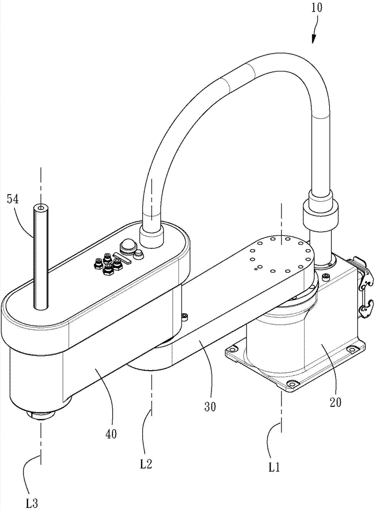
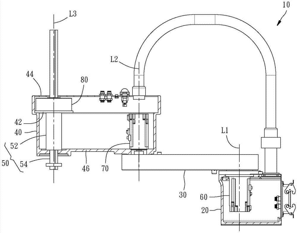
[0014] Please refer to the figures, the horizontal multi-joint mechanical arm 10 provided by a preferred embodiment of the present invention includes a base 20, a first cantilever 30, a second cantilever 40, a rod-shaped linear motor (shaft motor) 50, three Rotary motors 60, 70, 80, and a sleeve 90.

[0015] One end of the first cantilever 30 is arranged on the base 20 , the rotary motor 60 is arranged in the base 20 , and a rotating shaft (not shown in the figure) protrudes upwards, and the rotating shaft is connected with the first cantilever 30 , and can drive the first suspension arm 30 to rotate relative to the base 20 around a first imaginary axis L1.

[0016] One end of the second cantilever 40 is arranged on the other end of the first cantilever 30, the rotary motor 70 is arranged in the second cantilever 40, and protrudes downward from a rotating shaft (not shown in the figure), the rotating shaft Connected with the first cantilever 30; thus, the rotation motor 70 ca...


PUM


Abstract

The invention provides a selective compliance assembly robot. The selective compliance assembly robot comprises a base, a first cantilever arranged on the base and capable of rotating with a first hypothetical axis as the center relative to the base, a second cantilever arranged on the first cantilever and capable of rotating with a second hypothetical axis as the center relative to the first cantilever, a shaft motor and rotary motors. The shaft motor comprises a fixing piece arranged on the second cantilever and a shaft rod capable of moving along a third hypothetical axis relative to the fixing piece. The first hypothetical axis, the second hypothetical axis and the third hypothetical axis are substantially parallel to one another. The rotary motors are arranged on the second cantilever and capable of driving the shaft rod to rotate with the third hypothetical axis as the center. In this way, according to the selective compliance assembly robot, the shaft rod is high in drive efficiency, stable in drive and capable of being controlled easily and precisely, and the maintenance cost is lower due to the fact that parts are not prone to damage.

Description

technical field [0001] The present invention relates to a mechanical arm, in particular to a horizontal multi-joint mechanical arm (SCARA Robot). Background technique [0002] Please refer to the invention patent of Taiwan Patent Publication No. 201242731. The known horizontal multi-joint mechanical arm mainly includes a base, a first cantilever on the base, and a second cantilever on the first cantilever. , and a shaft vertically passing through the second cantilever, the first cantilever is driven by a first motor built in the base, and the second cantilever is driven by a second motor built in itself , and the shaft can be rotated and axially displaced separately or simultaneously by a relatively complicated driving method. [0003] In detail, the shaft is a ball screw with a spline groove, and a shaft driving device is also provided in the second cantilever, including two motors, two belts, and a spline nut sleeved on the shaft and a ball nut, the spline nut and the ba...

Claims


Application Information

Patent Timeline
Patent Type & Authority Applications(China)
IPC IPC(8): B25J9/06B25J9/04
CPCB25J9/044Y10T74/20317B25J18/04G05B2219/40301
Inventor 卓永财王福清林宗颖
Owner HIWIN TECH
Why Eureka
Eureka Blog
Learn More