
A water-proof socket

An anti-splashing and socket technology, applied in the base/casing, electrical components, coupling devices, etc., can solve the problems of unusable, easy to infiltrate the main body of the socket, easy to appear shallow water, etc., to achieve excellent anti-splashing water. Effect

Active Publication Date: 2017-08-18
BULL GRP CO LTD
View PDF15 Cites 0 Cited by
  • Summary
  • Abstract
  • Description
  • Claims
  • Application Information

AI Technical Summary

Problems solved by technology

The waterproof socket of this application protects the socket head through a waterproof cover to realize the rainproof function of the socket head; however, the socket is placed on the ground through the lower end of the socket body, and once the ground accumulates water, the accumulated water will easily seep into the socket body. Therefore it cannot be used on waterlogged ground
The waterproof socket in this application cannot meet the conditions of continuous light to moderate rain, and can be used in an outdoor environment (under continuous light to moderate rain, shallow water is prone to appear on the ground)

Method used


Image

  • A water-proof socket
  • A water-proof socket
  • A water-proof socket

Examples


Embodiment 1

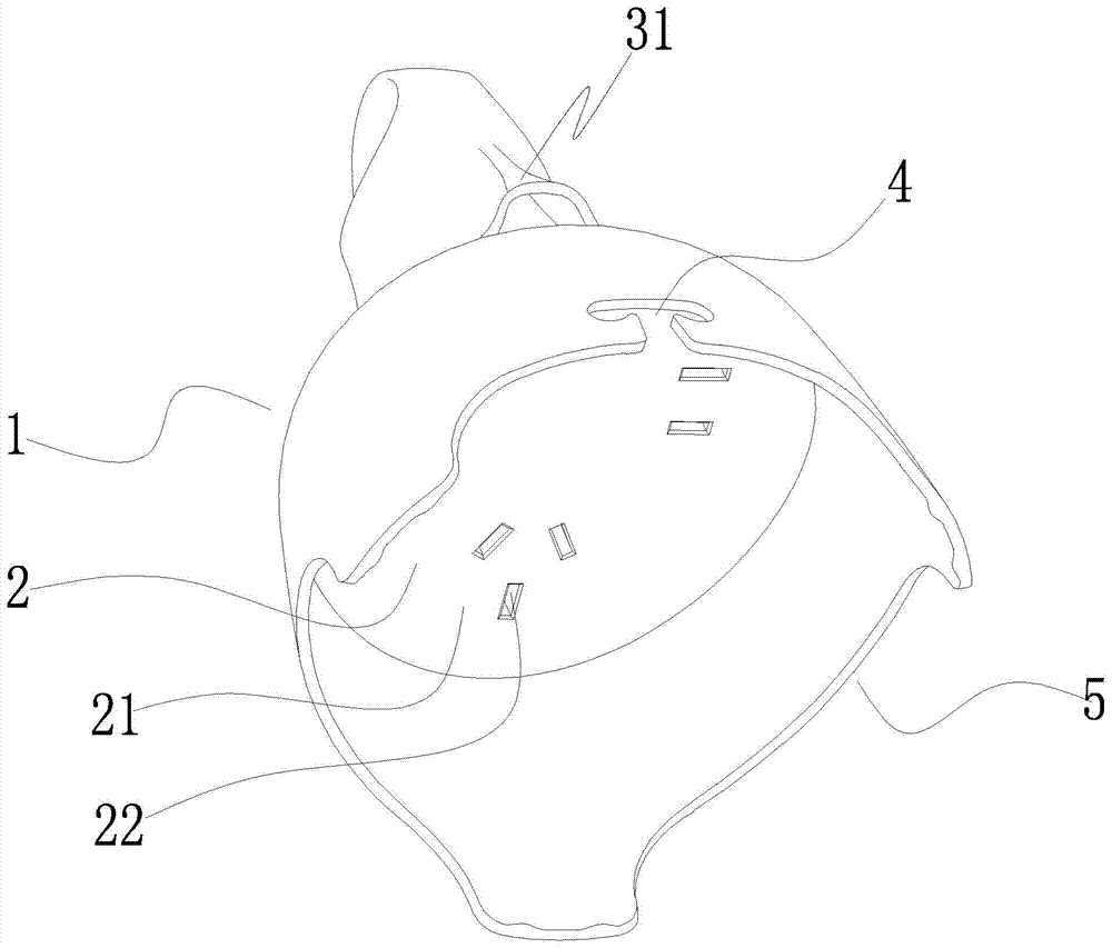
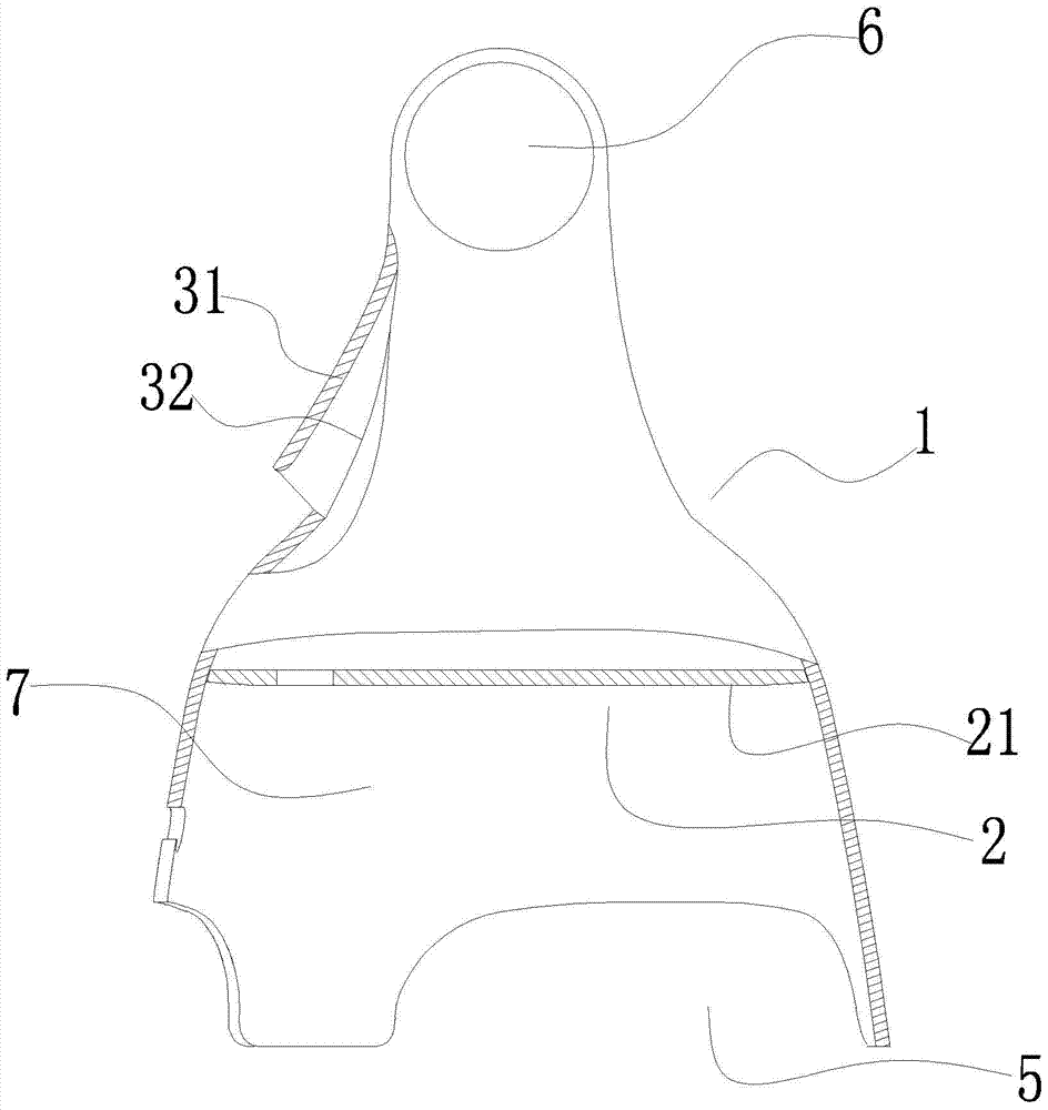
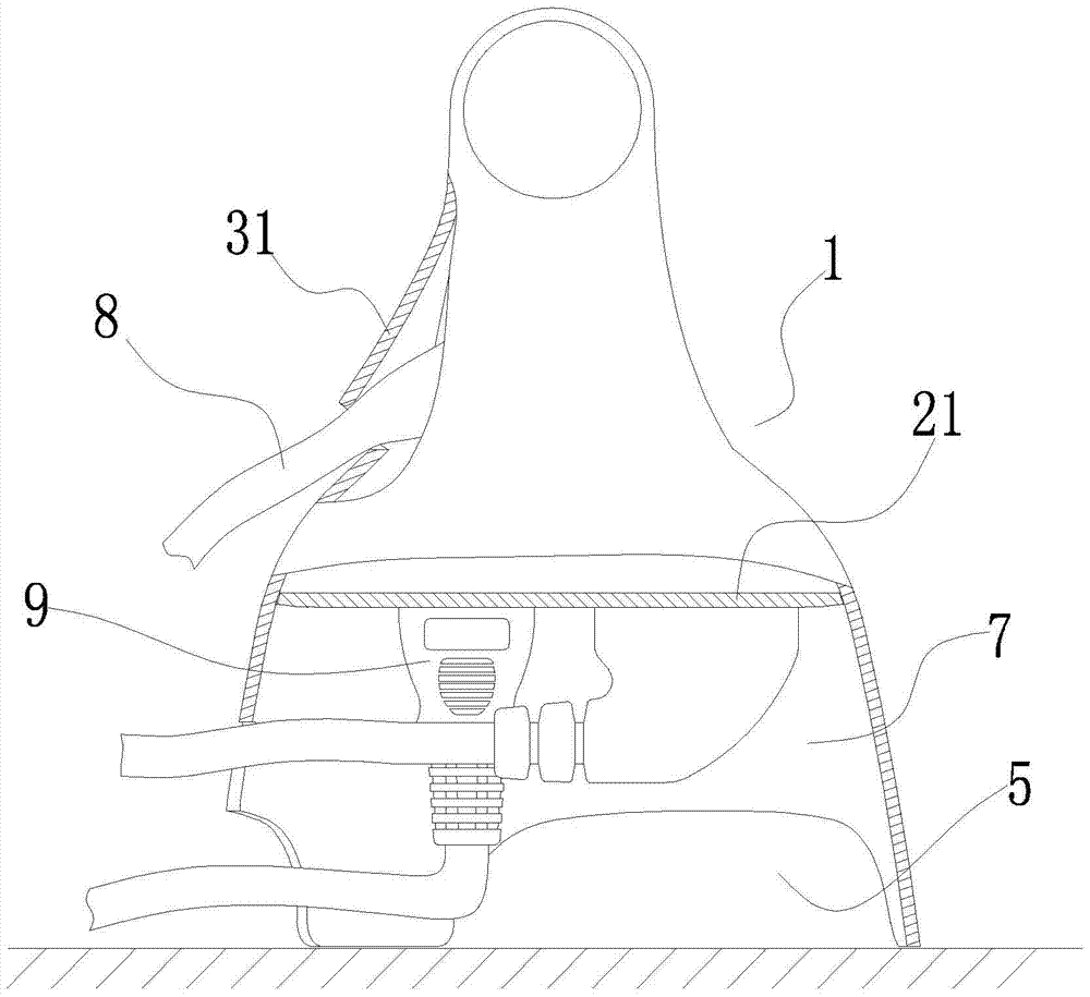
[0035] Embodiment 1: as figure 1 , figure 2 , image 3 As shown, a water-proof socket includes a socket cover body 1 with a closed upper end and an open lower end, a socket main body 2 and a socket power cord 8 arranged in the socket cover body. The lower end of the socket cover is used to support the anti-splash socket. The socket cover is integrally formed. The socket cover body is in the shape of a bell jar. The cross section of the socket cover is circular, and the cross section of the socket cover gradually increases from top to bottom. The top of the socket cover is provided with a hanging hole 6 . The bottom edge of the outer surface of the socket cover is provided with at least one wire-passing gap 5; the bottom edge of the socket cover outer surface in this embodiment is provided with three circumferentially evenly distributed wire-passing gaps, and the gap between two adjacent wire-passing gaps The socket cover forms the resting feet. At least one of the thre...

Embodiment 2

[0040] Embodiment 2: the remaining structure of this embodiment is with reference to embodiment 1, and its difference is:

[0041] like Figure 4 As shown, the socket cover body includes a socket cover main body 1 a and a wiring cover 1 b located above the socket cover main body. The upper and lower ends of the main body of the socket cover are open. The upper opening edge of the main body of the socket cover is provided with an inwardly extending annular limiting plate 12 , and the inner edge of the annular limiting plate is provided with an upwardly extending annular mounting sleeve 13 . The socket body is located in the socket cover body. Three circumferentially evenly distributed first counterbores 14 are provided on the annular limiting plate, and first connecting bolts are provided in each first counterbore. First bolt holes matched with the first connecting bolts are arranged on the jack panel. The jack panel is installed on the annular limiting plate, and the jack ...


PUM


Abstract

The invention discloses a waterproof socket, and aims at providing a waterproof socket which is outstanding in waterproofing function and meets the demand on waterproof use under the conditions that water is accumulated in a shallow level on the pavement and small to moderate rain occurs. The waterproof socket comprises a cover body of which the upper end is closed and while the lower end is opened, and a socket body arranged in the cover body; the socket body is positioned above the opening in the lower end of the cover body, comprising a plug-in hole panel which arranged in the cover body and divides the cover body into an upper space and a lower space; a socket hole is formed in the plug-in hole panel and faces the opening in the lower end of the cover body; the space in the cover body, positioned above the plug-in hole panel forms a mounting space for mounting inner parts of the socket; the space in the cover body, positioned between the plug-in panel and the opening in the lower end of the cover body forms a plug storing space.

Description

technical field [0001] The invention relates to a socket, in particular to a water-proof socket. Background technique [0002] Existing sockets / converters are divided into two categories: one without protection against ingress of water; the other with protection against ingress of water. Existing anti-water sockets / converters can be initially divided into professional-level anti-water and simple-level anti-water; and the anti-water structure of existing anti-water sockets / converters is dominated by isolation, which uses sealed The ring, anti-water cover, partition and other structures are isolated to prevent water ingress. [0003] The anti-water structure of the professional-grade anti-water socket / converter has complex internal and external structures; the internal structure needs to use springs, contacts and other parts, the production is high-precision, and the movement mechanism is complex; when the external seal is sealed, a sealing ring is required and matching plug...

Claims


Application Information

Patent Timeline
Patent Type & Authority Patents(China)
IPC IPC(8): H01R13/52
CPCH01R13/5202H01R13/5227
Inventor 周飞龙成瀚朱俊杰陆展科
Owner BULL GRP CO LTD
Learn More