
a toggle switch

A technology for switching switches and connectors, applied in the field of switches, can solve the problems of cumbersome installation and debugging, high machining accuracy, and incorrect contact of reeds, such as electrical faults.

Active Publication Date: 2017-01-11
BEIJING BBEF SCI & TECH
View PDF2 Cites 0 Cited by
  • Summary
  • Abstract
  • Description
  • Claims
  • Application Information

AI Technical Summary

Problems solved by technology

This type of switch requires high processing precision, cumbersome installation and debugging, and is prone to electrical failures due to false contact of the reed or a small number of contact reeds.

Method used


Image

  • a toggle switch
  • a toggle switch
  • a toggle switch

Examples


Embodiment Construction

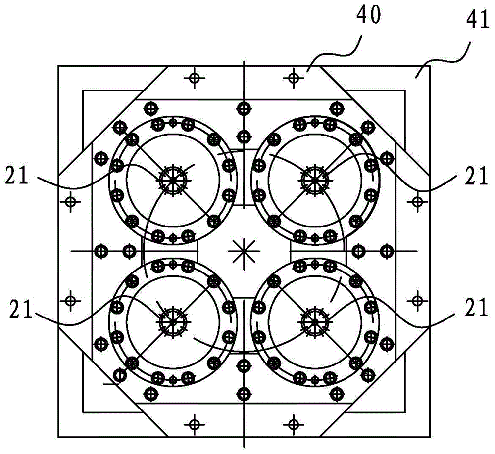
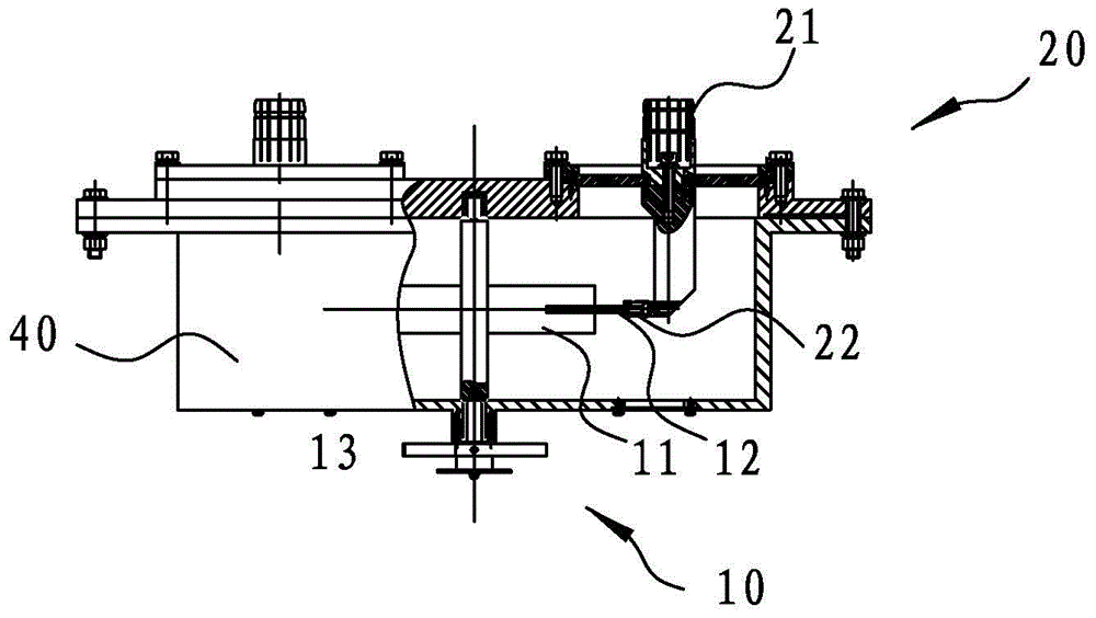
[0022] In order to further explain the technical means and effects of the present invention to achieve the intended purpose of the invention, the specific implementation, structure, characteristics and effects of the switch proposed according to the present invention will be described in detail below in conjunction with the accompanying drawings and preferred embodiments. The description is as follows.

[0023] The aforementioned and other technical contents, features and effects of the present invention will be clearly presented in the following detailed description of preferred embodiments with reference to the drawings. Through the description of specific embodiments, it should be possible to obtain a deeper and more specific understanding of the technical means and effects of the present invention to achieve the intended purpose, but the attached drawings are only for reference and description, and are not used to explain the present invention. be restricted.

[0024] see...


PUM


Abstract

A diverter switching comprises a rotor component, connectors, a driving mechanism and a shell. The rotor component comprises knives, and at least two contacts are arranged at a certain interval on each knife; each connector comprises an external plug and a contact seat connected with the external plug; the contacts can be switched in the contact seats and retained in the same; the at least two contacts on the same knife can be switched in the contact seats of different connectors at the same time to realize connection of the different connectors; the driving mechanism arranged outside the shell is connected with a rotating shaft of the rotor component which is arranged in the shell; the connectors are arranged on the shell, the external plugs are positioned outside the shell, and the contact seats are positioned in the shell. The driving mechanism drives the rotor component to rotate relative to the shell so as to enable the knives to rotate to different positions, and at different positions, the contacts of the knives are switched into the contact seats of different connectors at the same time to realize connection of the different connectors, so that switching of the knives among the different connectors is realized.

Description

technical field [0001] The present invention relates to a switch, in particular to a switching switch for automatic switching between main and standby machines and antennas or dummy loads of medium and short-wave broadcast transmitting systems. Background technique [0002] The main and standby machines of the medium and short wave transmitting system for broadcast communication need to be switched between the antenna or the dummy load. Usually, the main and standby machines of the medium and short wave transmitting system for broadcast communication are switched between the antenna or the dummy load through a switch. Switching, the transmission power of the main machine and the standby machine is sent to the antenna or dummy load. At present, the switch commonly used for automatic switching between the main and standby machines of medium and short wave broadcasting transmission systems and antennas or dummy loads mainly adopts the regional reed friction type inside, that is...

Claims


Application Information

Patent Timeline
Patent Type & Authority Patents(China)
IPC IPC(8): H01H21/54
CPCH01H3/44H01H21/54H01H31/36
Inventor 陈春雨毛雄天王世来
Owner BEIJING BBEF SCI & TECH
Learn More