
A kind of array substrate, liquid crystal panel and display device

A technology for array substrates and substrate substrates, applied in nonlinear optics, instruments, optics, etc., can solve problems affecting the yield rate of liquid crystal panels, electrostatic breakdown, etc.

Active Publication Date: 2017-10-10
BOE TECH GRP CO LTD +1
View PDF5 Cites 0 Cited by
  • Summary
  • Abstract
  • Description
  • Claims
  • Application Information

AI Technical Summary

Problems solved by technology

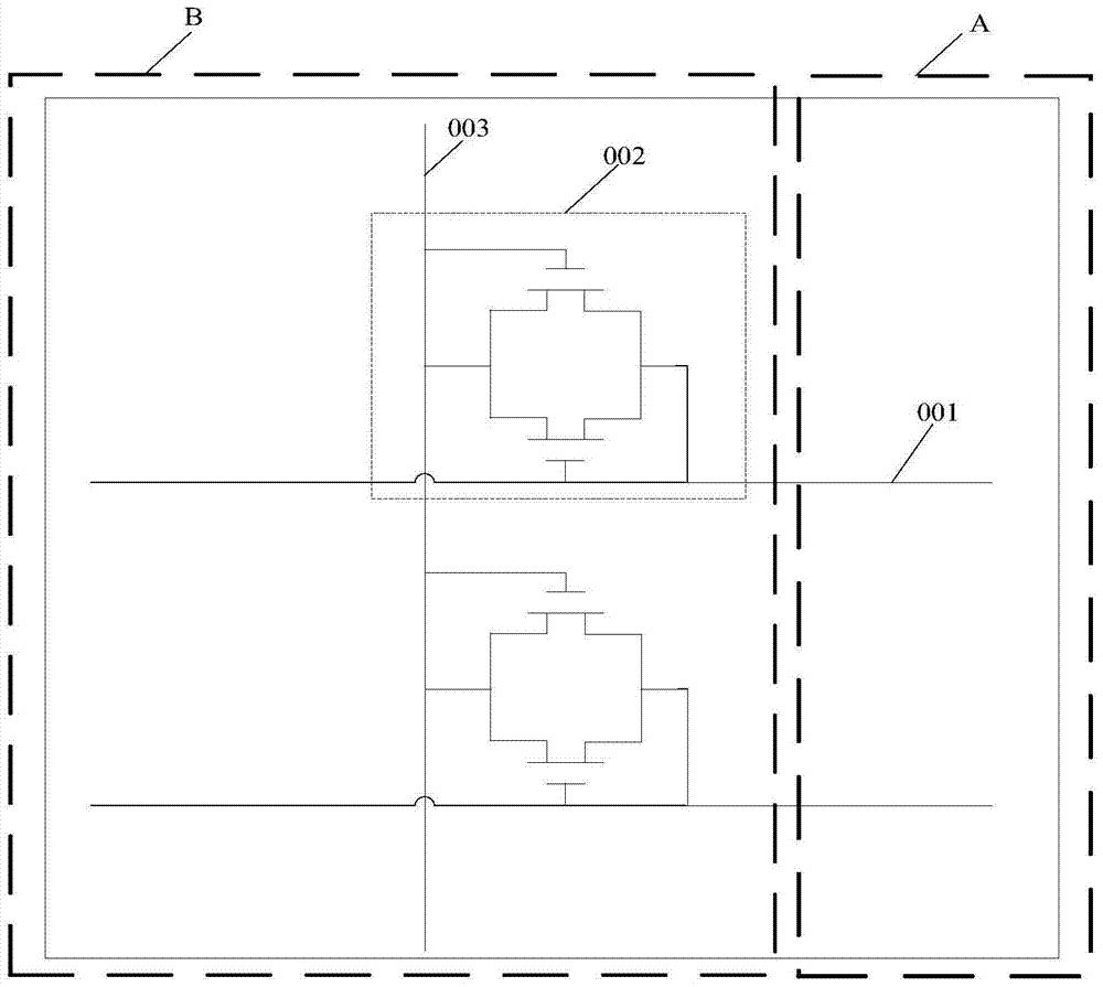
[0003] In the existing array substrate design, such as figure 1 As shown, the end of the signal line 001 (gate line or data line) is generally provided with an electrostatic protection circuit 002 and a shorting bar 003 connected to the electrostatic protection circuit 002 located in the surrounding area B. When static electricity comes, the electrostatic protection circuit 002 is turned on. The shorting bar 003 connected to the electrostatic protection circuit 002 can lead out the instantaneous high voltage of static electricity in the display area A. However, because the static electricity is generated too quickly, when the static electricity disappears, the electrostatic protection circuit 002 will stop working immediately, and the shorting bar 003 will usually It is too late to export the electrostatic charge, and electrostatic breakdown will still occur due to the accumulation of electrostatic charge, which directly affects the yield of LCD panels

Method used


Image

  • A kind of array substrate, liquid crystal panel and display device
  • A kind of array substrate, liquid crystal panel and display device
  • A kind of array substrate, liquid crystal panel and display device

Examples


Embodiment Construction

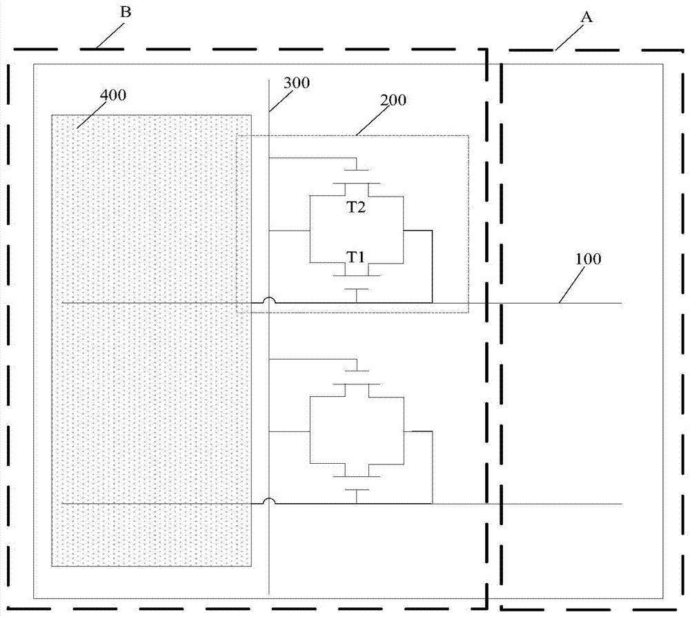
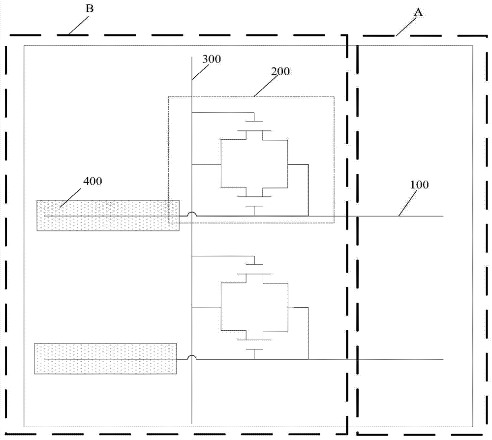
[0027] The specific implementation manners of the array substrate, liquid crystal panel and display device provided by the embodiments of the present invention will be described in detail below with reference to the accompanying drawings.

[0028] Wherein, the shapes and sizes of the components in the array substrate in the drawings do not reflect the real scale, and the purpose is only to schematically illustrate the content of the present invention.

[0029] An embodiment of the present invention provides an array substrate, such as Figure 2a and 2b As shown, it includes: a base substrate, a plurality of gate lines and data lines arranged on the base substrate in the display area A and the peripheral area B surrounding the display area A, and arranged at one end of at least one gate line or data line 100 The electrostatic protection circuit 200 correspondingly connected to the gate line or the data line 100, and the shorting bar 300 correspondingly connected to the electro...


PUM


Abstract

The invention discloses an array base plate, a liquid crystal display panel and a display device. The array base plate comprises a substrate base plate, a plurality of grid lines and data lines arranged on the substrate base plate, electrostatic protection return circuits arranged at one ends of one or more grid lines or data lines and connected with the grid lines or the data lines correspondingly and short-circuit rods correspondingly connected with the electrostatic protection return circuits, located on a perimeter zone and used for transmitting common voltage signals; the array base plate further comprises a transparency electrode layer located on the perimeter zone; the transparency electrode layer is electrically connected with each short-circuit rod through via holes; the projection of the transparency electrode layer and the grid lines or the data lines correspondingly connected with each electrostatic protection return circuit on the substrate base plate has an overlapping zone, and a filter capacitor is formed in the overlapping zone; when static electricity comes, the electrostatic protection return circuits are communicated, electrostatic charges are stored in the filter capacitor, and when the static electricity disappears, the electrostatic protection return circuits do not stop working immediately, the filter capacitor still maintains an open state, and the electrostatic charges are released slowly; accordingly, the role of electrostatic protection is played.

Description

technical field [0001] The invention relates to the field of display technology, in particular to an array substrate, a liquid crystal panel and a display device. Background technique [0002] Currently, the phenomenon of Electro-Static Discharge (ESD) is common in liquid crystal display products. ESD is a kind of static electricity accumulation, which transfers and releases static electricity between different objects. The time of static electricity discharge is very short, generally only on the nanosecond level. The discharge of static electricity in such a short period of time will generate a very large instantaneous current, so high When the current passes through the integrated circuit, the device will be burned, resulting in the circuit not working properly. Therefore, the occurrence of ESD in liquid crystal display products usually causes electrostatic breakdown short circuit or open circuit on peripheral design lines. [0003] In the existing array substrate design...

Claims


Application Information

Patent Timeline
Patent Type & Authority Patents(China)
IPC IPC(8): G02F1/1362G02F1/1343
CPCG02F1/1345G02F1/136286
Inventor 刘莎
Owner BOE TECH GRP CO LTD
Learn More