Outdoor environment-friendly lighting device

A lighting device, outdoor environmental protection technology, applied in outdoor lighting, lighting devices, fixed lighting devices, etc., can solve problems such as increased failure rate, high use cost, and multiple equipment structures, so as to increase the number of rotations and increase power generation efficiency Effect

Inactive Publication Date: 2015-06-10
CHENGDU FUYANG TECH DEV
View PDF11 Cites 14 Cited by
  • Summary
  • Abstract
  • Description
  • Claims
  • Application Information

AI Technical Summary

Problems solved by technology

[0004] With the development of solar technology, the technology of using solar energy on street lamps has been very mature, but the current production cost of solar panels is high, resulting in the high cost of using solar street lamps, so without affecting the normal use of solar street lamps, as far as possible Possible reduction of production cost will be the main problem to be overcome at present
At present, there is a requirement in the market to change the solar circuit to save the electricity consumption of LED lights, thereby reducing electricity consumption, but this is to achieve the requirement of saving electricity by sacrificing the brightness of LED lights, and adding devices such as light chasers, so that Solar energy can absorb more electric energy, but a lot of equipment needs to be added. Although the electric energy is increased, the production cost remains high, the use cost is high, there are too many equipment structures, the failure rate increases, and it is not easy to popularize
In order to save energy and protect the environment, the street lamps in the general community are all solar street lamps, which convert solar energy into electrical energy and store it in the battery to supply power to the street lamps. However, during use, once the weather is bad or the battery fails, the street lamp cannot be used. , causing inconvenience to residents' daily life

Method used


Image

  • Outdoor environment-friendly lighting device
  • Outdoor environment-friendly lighting device
  • Outdoor environment-friendly lighting device

Examples


Embodiment Construction

[0027] specific implementation plan

[0028] Preferred embodiments of the present invention will be described in detail below in conjunction with the accompanying drawings.

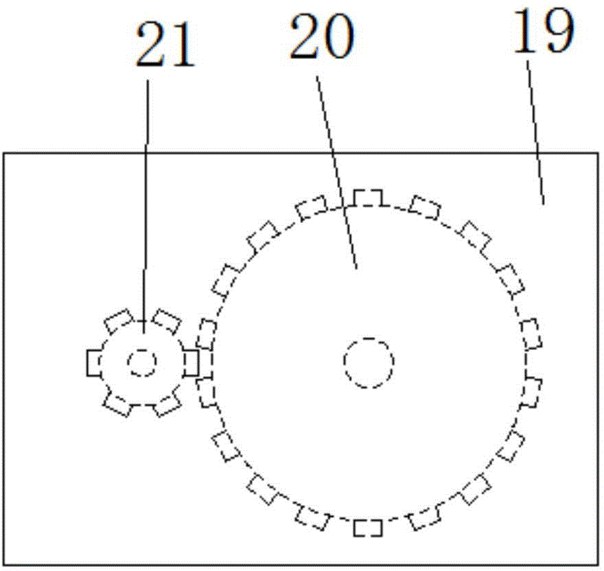
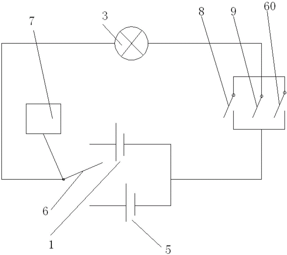
[0029] figure 1 A specific embodiment of the present invention is shown: an outdoor environment-friendly lighting device, including a lamp post 10 and a street lamp 3 arranged on the top of the lamp post 10, a lamp housing 11 is arranged above the street lamp 3, and a solar energy is provided on the upper part of the lamp post 10 The power generation system and the wind power generation system, the bottom of the lamp post 10 is provided with a storage battery 1, the solar power generation system includes a solar panel 2 and a photoelectric conversion circuit, the solar panel 2 is connected to the storage battery 1 through a photoelectric conversion circuit, and the wind power generation system includes a wind power generation system The device and the wind charging circuit, the wind power generating devi...


PUM


Abstract

The invention discloses an outdoor environment-friendly lighting device. The outdoor environment-friendly lighting device comprises a lamp post and a street lamp arranged on the top part of the lamp post; the upper part of the street lamp is provided with a lamp shell, and the upper part of the lamp post is provided with a solar energy power generating system and a wind turbine system; the bottom part of the lamp post is provided with a storage battery, and a solar cell panel arranged on the top end of the lamp post is connected with the storage battery through a photovoltaic conversion circuit; the wind turbine system comprises a wind power generating device and a wind charging circuit, the street lamp and the storage battery are formed to be a first series linking circuit, and the street lamp and the external power source are formed to be a second serial linking circuit; the first series linking circuit and the second series linking circuit are formed to be a parallel linking circuit through a selector switch; a power quantity sensor is arranged on the storage battery, and the selector switch is electrically connected with the power quantity sensor. The outdoor energy-saving floodlight can accumulate power through solar energy, wind energy and water energy, and also can select different power sources according to the power quantity of the storage battery, so as to ensure the normal use of the street lamp.

Description

technical field [0001] The invention relates to the field of energy-saving lamps, in particular to an outdoor environment-friendly lighting device. Background technique [0002] As an existing general road lighting fixture, outdoor lighting plays an important lighting role in night traffic. Current street lamps are composed of lamps and light poles, and lamps generally include spherical bulbs, reflective bowls, metal shells and outer covers. For example, Chinese patent literature once disclosed an outdoor street lamp [Chinese Patent No.: ZL200520030685.0; Authorized Announcement No.: CN2783118Y], which includes an independent street lamp pole, at least two light sources are arranged on the street lamp pole and control these light sources The time-controlled power line switching mechanism. It is electric energy that provides luminous energy for lamps. Saving electric energy and improving the utilization rate of electric energy can save resources. Therefore, the power loss r...

Claims


Application Information

Patent Timeline
Patent Type & Authority Applications(China)
IPC IPC(8): F21S9/03F21S9/02F21S9/04F21V23/00F21W131/103F21Y101/02F21Y115/10
CPCY02B20/72F21S8/086F21S9/026F21S9/028F21S9/035F21S9/043F21S9/046F21V23/003F21V23/0471F21W2131/103
Inventor 车国容
Owner CHENGDU FUYANG TECH DEV
Why Eureka
Try Eureka