
Gastric tube

A gastric tube and tube body technology, which is applied to gastric tube. It can solve problems such as facial skin damage, gastric tube extraction, allergies, itching, etc.

Inactive Publication Date: 2015-06-10
PEKING UNIV THIRD HOSPITAL
View PDF15 Cites 4 Cited by
  • Summary
  • Abstract
  • Description
  • Claims
  • Application Information

AI Technical Summary

Problems solved by technology

The long-term bonding of the tape and the friction between the winding pipeline and the patient's face will cause facial skin damage, allergies and itching of the patient. The patient scratches the itchy part consciously or unconsciously, causing local infection and easily causing the fixing tape to slip off , thus causing the gastric tube to be pulled out, resulting in adverse nursing events

Method used


Image

  • Gastric tube
  • Gastric tube
  • Gastric tube

Examples


Embodiment 1

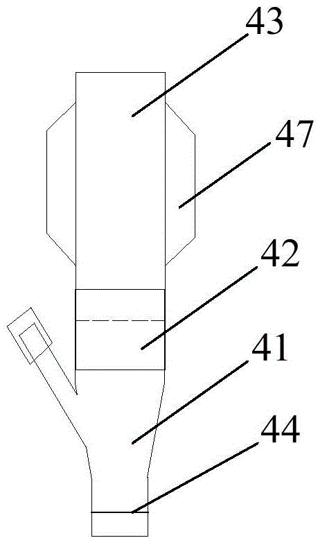
[0038] figure 1 It is a structural schematic diagram of a gastric tube according to a preferred embodiment. Such as figure 1 As shown, the stomach tube includes a first tube body 1 with a closed bottom and a plurality of round holes on the bottom wall, a first tube positioning seat 2 and a second tube body 3 .

[0039] The first tube body positioning seat includes a seat body 21 and a positioning member 22 arranged on the seat body. Both sides of the seat body 21 are respectively connected with elastic bands 23 , and the other end of each elastic band 23 is provided with earmuffs 24 . The positioning part includes an upper clamp and a lower clamp, and the upper clamp and the lower clamp are opposed to form a hole-shaped engaging part, and the first tube body positioning seat 2 is selectively fixed to the first tube body through the hole-shaped engaging part 1 anywhere in the upper middle.

[0040] As one of the preferred embodiments among the various embodiments, the lower...

Embodiment 2

[0057] The structure of the gastric tube in this embodiment is partially similar to that of the gastric tube in Embodiment 1, the difference lies in the connection modes of the first tube body and the second tube body. In this embodiment, the first pipe body and the second pipe body form a hidden connection.

[0058] Figure 4 It is a structural schematic diagram of a gastric tube according to another preferred embodiment. Such as Figure 4 As shown, the stomach tube includes a first tube body 1 with a closed bottom and a plurality of round holes on the bottom wall, a first tube positioning seat 2 and a second tube body 3 .

[0059] The second pipe body 3 is sleeved inside the first pipe body 1 , and the connecting end of the second pipe body 3 is in sealing connection with the inner wall of the first pipe body 1 . The periphery of the connection end of the second pipe body 3 is equipped with an elastic member 5, and the elastic member 5 abuts against the inner wall of the ...


PUM


Abstract

An embodiment of the invention discloses a gastric tube. The gastric tube comprises a first tube body, a first tube body locating base and a second tube body, wherein the bottom of the first tube body is closed, and a plurality of circular holes are formed in the wall of the bottom of the first tube body. The first tube body locating base comprises a base body and a locating part arranged on the base body, wherein elastic bands are connected to the two sides of the base body, and an ear cap is arranged at the other end of each elastic band. The locating part comprises an upper clamp and a lower clamp, wherein the upper clamp and the lower clamp are relatively arranged to form a hole-shaped clamping portion, and the first tube body is selectively fixed to any one position of the upper portion of the first tube body through the hole-shaped clamping portion. The connecting end of the second tube body is detachably connected to the top of the first tube body or, hidden connection is formed between the connecting end of the second tube body and the first tube body. The gastric tube has the advantages that multiple functions that enteral nutrition fluid, intake medicine and other liquid food are provided, gastric juice is sucked and gastrointestinal decompression is conducted are given consideration to, and the phenomenon that part of pipelines have to wind around and adhere to the face of a patient can be avoided.

Description

technical field [0001] The invention relates to the field of medical devices, in particular to a stomach tube. Background technique [0002] The gastric tube is inserted through the nostril, passes through the pharynx, and reaches the stomach through the esophagus. When the gastric tube is used to provide food and nutrition, its length of 0.7 to 1 meter can meet the length needs of the patient's nasal cavity to the stomach. However, since the gastric tube needs to be connected to the suction device when it is used for suctioning gastric juice and decompression, in order to take into account both purposes, the length of the gastric tube currently used in medical institutions is usually about 1.5 meters. [0003] Since the length of the existing gastric tube is greater than the length from the patient's nasal cavity to the stomach, in addition to gastric juice suction, the tube body exposed outside the patient's nasal cavity is usually wrapped and pasted on the patient's face...

Claims


Application Information

Patent Timeline
IPC IPC(8): A61M25/00A61J15/00
Inventor 刘桂花田兆兴
Owner PEKING UNIV THIRD HOSPITAL
Learn More