
A method for unobstructed positioning of surgical instruments based on two binocular vision systems

A binocular vision system and surgical instrument technology, which is applied in the field of unobstructed positioning of surgical instruments, can solve the requirements of reducing the motion accuracy of the robotic arm, reduce the cost of the robotic arm, and easily block the markers, etc., and meet the requirements of reducing the motion accuracy , reduce costs, and avoid the effect of coordinate transformation operations

Active Publication Date: 2017-04-19
SOUTH CHINA UNIV OF TECH
View PDF6 Cites 0 Cited by
  • Summary
  • Abstract
  • Description
  • Claims
  • Application Information

AI Technical Summary

Problems solved by technology

[0004] The purpose of the present invention is to overcome the shortcomings and shortcomings of the optical positioning technology in the prior art that the light is easily blocked during the operation, and provide a non-blocking positioning method for surgical instruments based on two binocular vision systems. The method effectively solves the problem that the markers are easily blocked during the operation, and at the same time reduces the requirements for the movement accuracy of the robotic arm, reduces the cost of the robotic arm, and has important application value in the field of surgical navigation

Method used


Image

  • A method for unobstructed positioning of surgical instruments based on two binocular vision systems
  • A method for unobstructed positioning of surgical instruments based on two binocular vision systems

Examples


Embodiment

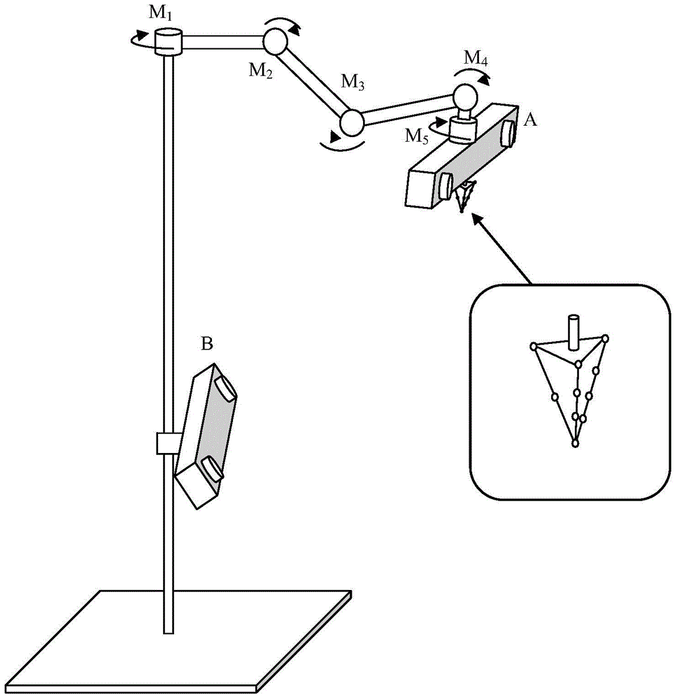
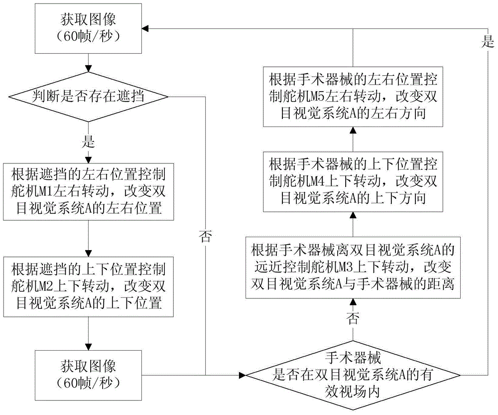
[0025] Such as figure 1 As shown, an unobstructed positioning method for surgical instruments based on two binocular vision systems is realized through the following steps:

[0026] (1) Fix the binocular vision system A (hereinafter referred to as A) to the front end of the robot arm and move with the robot arm. The binocular vision system consists of two near-infrared cameras and brackets that fix their positions. Initialize the position of the robotic arm so that the optical axis of the two cameras of A is level with the ground. The center of the connection between the two cameras is on the rotating shaft of the robotic arm servo M5. Such as figure 1 shown. Take the center of the line connecting the two cameras of A as the origin, take the direction of the line connecting the two cameras as the X-axis, take the direction from the left camera to the right camera as the X-axis direction, and take the vertical upward as the Z-axis to establish a Cartesian coordinate system as...


PUM


Abstract

The invention discloses a non-blocking positioning method for a surgical instrument based on two binocular vision systems. The method comprises the following steps: 1, mounting A at the front end of a mechanical arm, and enabling the A to move along with the mechanical arm; 2, fixing B in the middle of a mechanical arm bracket, and fixing a marker on the A so as to realize the positioning of the B on the A; 3, acquiring the position of the surgical instrument in an A coordinate system, and determining the position of the surgical instrument in a world coordinate system according to the position of the A in the B; 4, when the surgical instrument is blocked by an obstacle in front of the surgical instrument, driving the A to bypass the obstacle under the control of the mechanical arm, and acquiring the position of the surgical instrument in a new A coordinate system; 5, positioning the moved A again by the B, and realizing the non-blocking positioning on the surgical instrument through spatial coordinate transformation. The non-blocking positioning method has the advantages that the problem that the marker is easily blocked in the surgical process is effectively solved, and the requirement on the motion precision of the mechanical arm is lowered.

Description

technical field [0001] The invention relates to a surgical navigation technology, in particular to an unobstructed positioning method for surgical instruments based on two binocular vision systems. Background technique [0002] The optical positioning equipment in surgical navigation is generally fixed by two fixed-focus cameras on a bracket to form a fixed effective field of view. Surgical instruments can be accurately positioned when they move within the effective field of view of the cameras. However, the current optical positioning technology has two main disadvantages: 1) The optical imaging equipment is limited by the effective field of view of the camera, so that the operation must be completed within the effective field of view of the camera. 2) The light is easily blocked during the operation. The doctor can only adjust the imaging equipment or surgical instruments to a reasonable position to complete the positioning, which brings great inconvenience to the doctor....

Claims


Application Information

Patent Timeline
Patent Type & Authority Patents(China)
IPC IPC(8): A61B90/10
Inventor 杨荣骞关沛峰林钦永司璇蔡肯肖伟虎陈秀文
Owner SOUTH CHINA UNIV OF TECH
Learn More