Embedded Ethernet interface for optical fiber gyrocompass

A fiber optic gyroscope, network interface technology, used in electrical components, transmission systems, etc.

Inactive Publication Date: 2015-06-03
哈尔滨功成科技创业投资有限公司
View PDF0 Cites 1 Cited by
  • Summary
  • Abstract
  • Description
  • Claims
  • Application Information

AI Technical Summary

Problems solved by technology

[0005] The purpose of the present invention is to design an Ethernet interface based on an embedded system for the traditional serial port transmission method of the fiber optic gyro compass, which cannot carry out a large amount of remote information transmission , enabling the system to be remotely monitored and accessed via a PC, and to communicate, exchange information and data with other embedded systems with network capabilities

Method used


Image

  • Embedded Ethernet interface for optical fiber gyrocompass
  • Embedded Ethernet interface for optical fiber gyrocompass
  • Embedded Ethernet interface for optical fiber gyrocompass

Examples


Embodiment Construction

[0020] The present invention is described in more detail below in conjunction with accompanying drawing example:

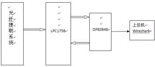
[0021] An embedded Ethernet network interface of a fiber optic gyro compass, which consists of a microprocessor, an Ethernet module, an Ethernet controller, and a main register, wherein the microprocessor uses the LPC1758 of the hardware system Cortex-M3 series, and the Ethernet module is LPC1758 On-chip.

[0022] It is characterized in that DP83848 is used as the underlying physical chip.

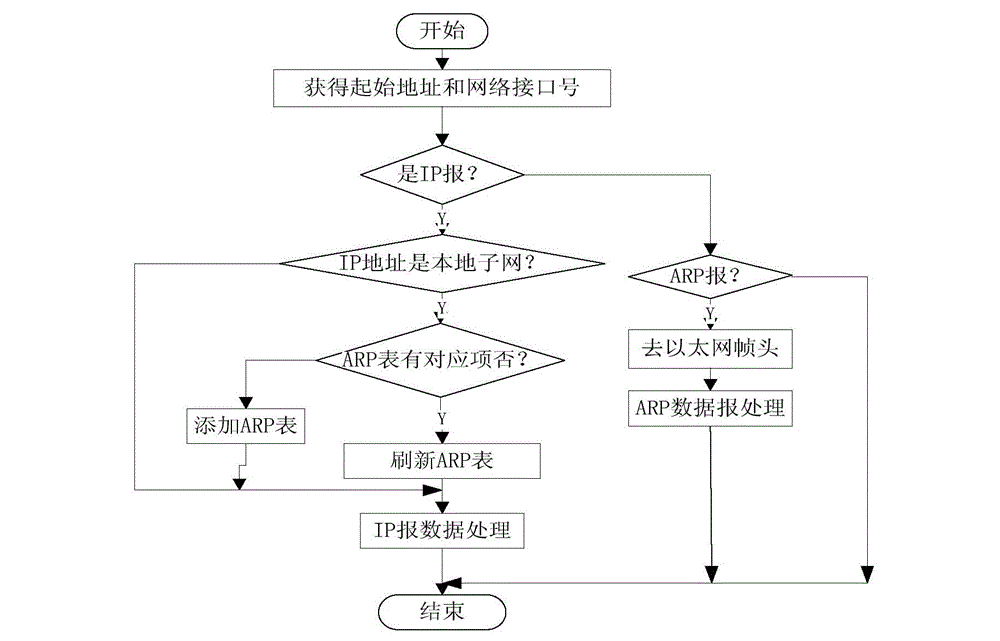
[0023] It is characterized in that the Ethernet layer data receiving module also obtains the network interface number while obtaining the starting address.

[0024] It is characterized in that the Ethernet layer data sending module also obtains the target IP while obtaining the data information of the upper layer protocol.

[0025] combine figure 1 , figure 1 It is a system principle structural diagram of the present invention; the LPC1758 of the hardware system Cortex-M3 ...


PUM


Abstract

The invention discloses an embedded Ethernet interface for an optical fiber gyrocompass, which comprises a microprocessor, an Ethernet module, an Ethernet controller, and a main register. An LPC1758 of a hardware system Cortex-M3 series serves as the microprocessor, the LPC1758 on-chip Ethernet module is used, and the Ethernet controller realizes a data link layer function in the system. The Ethernet module comprises the main register which can be recognized by software. Inner data processing is included. The Ethernet module is accessed via an advanced high-performance bus AHB. The main register and an MAC are connected onto a data transmitting and receiving channel. A DMA is connected onto an AHB interface module. The Ethernet module provides an AHB main connection mode. An inner chip SRAM can be allowed to be accessed to read described status words, and data are read and written to the Ethernet module in a buffer area.

Description

technical field [0001] The invention relates to an embedded system, in particular to an embedded Ethernet interface. Background technique [0002] Optical systems with no moving parts can detect a unique physical phenomenon of rotation relative to inertial space, now known as the Sagnac effect. Since the first fiber optic gyroscope appeared in 1976, significant progress has been made in the research and development of fiber optic gyroscopes in the following years, and fiber optic gyroscopes will become the most important new gyroscope technology in the 21st century. Compared with traditional electromechanical gyroscopes, fiber optic gyroscopes have the advantages of small size, high precision, short start-up time, wide dynamic range, light weight, low power consumption, all-solid-state, and can be integrated. With the mature production technology of large-scale and low-cost fiber optic gyro, the fiber optic gyro compass will become a new star in ship navigation. [0003] N...

Claims


Application Information

Patent Timeline
IPC IPC(8): H04L29/10
Inventor 白璐杨亮
Owner 哈尔滨功成科技创业投资有限公司
Why Eureka
Try Eureka