Photoelectric Mixed Connector

An optical connector, optoelectronic hybrid technology, applied in the direction of connection, connecting device parts, instruments, etc., can solve the problem of large loss of optical signal, ensure the performance, the accuracy of assembly position is easy to ensure, and solve the problem of excessive loss of optical signal. big effect

Inactive Publication Date: 2017-02-22
CHINA AVIATION OPTICAL-ELECTRICAL TECH CO LTD
View PDF4 Cites 0 Cited by
  • Summary
  • Abstract
  • Description
  • Claims
  • Application Information

AI Technical Summary

Problems solved by technology

[0004] The purpose of the present invention is to provide a photoelectric hybrid connector to solve the problem of excessive optical signal loss of the photoelectric hybrid connector

Method used


Image

  • Photoelectric Mixed Connector
  • Photoelectric Mixed Connector
  • Photoelectric Mixed Connector

Examples


Embodiment Construction

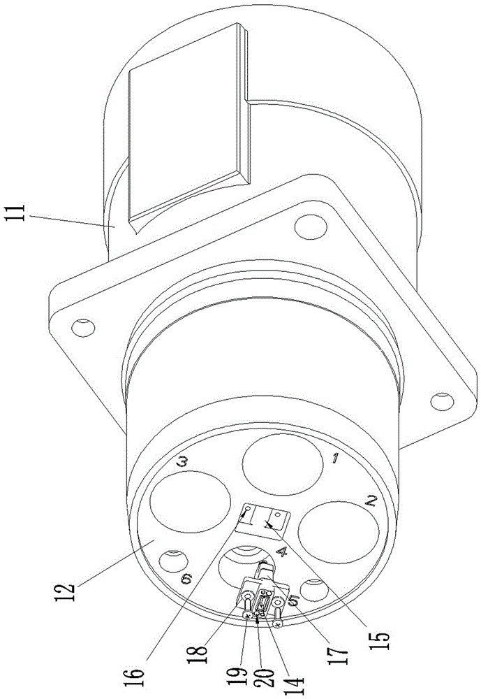
[0020] Embodiment 1 of the photoelectric hybrid connector, such as Figure 1-4 As shown, the photoelectric hybrid connector includes a housing 11 , an insulator 12 , an electrical contact 13 and an optical contact 14 .

[0021] The housing 11 is a mounting disk housing, and its structure is in the prior art, so it will not be repeated here.

[0022] The electrical contact 13 is fixedly mounted on the insulator 12. In this embodiment, the electrical contact 13 is a high-current contact, and its structure is in the prior art, so it will not be repeated here. In addition to being equipped with electrical contacts 13, an assembly hole 15 is also provided on the insulator 12, and the assembly hole 15 is used to assemble a corresponding optical connector. In this embodiment, the assembly hole 15 is surrounded by each electrical contact 13 The position between them is specifically a step hole, and a screw hole 16 is provided on the step surface.

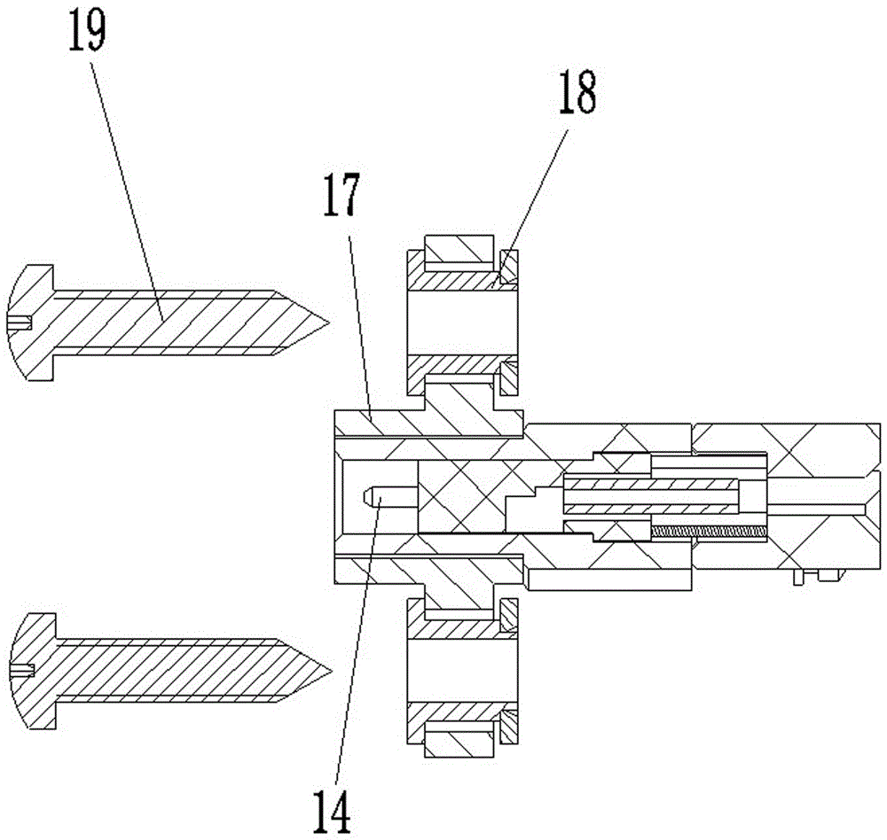
[0023] The optical contact 14 is t...


PUM


Abstract

The invention relates to the field of signal connectors, in particular to a photoelectric hybrid connector. The photoelectric hybrid connector comprises a shell, an insulation body, an electric contact element and an optical contact element; the optical contact element is a contact element of an optical connector assembled on the insulation body; the optical connector is assembled in an assembling hole, corresponding to the optical connector, in the insulation body. The optical contact element of the photoelectric hybrid connector is the contact element of the optical connector assembled on the insulation body and the optical connector is assembled in the assembling hole, corresponding to the optical connector, in the insulation body, so that in a manufacturing process, after the electric contact element is assembled, the optical contact element is then additionally arranged, at this moment, the assembly position precision of the optical contact element is ensured more easily, and thus the performances of the optical contact element can be ensured, and the problem of large optical signal loss of the photoelectric hybrid connector is further solved.

Description

technical field [0001] The invention relates to the field of signal connectors, in particular to a photoelectric hybrid connector. Background technique [0002] In recent years, with the continuous development and popularization of optical fiber transmission technology, more and more fields have begun to use optical fiber connectors, especially in some high-current electrical equipment, the application range of optical fiber transmission technology is also expanding , with the emergence of some occasions that need to transmit both current signals and optical signals, photoelectric hybrid connectors emerged as the times require. [0003] As the name suggests, the photoelectric hybrid connector can not only transmit high-current signals as power transmission components, but also transmit optical signals as signal transmission components. The existing photoelectric hybrid connector includes a housing, an insulator assembled in the housing, and an electrical contact and an opti...

Claims


Application Information

Patent Timeline
Patent Type & Authority Patents(China)
IPC IPC(8): H01R13/40H01R13/629G02B6/38
CPCG02B6/2817
Inventor 徐仁红
Owner CHINA AVIATION OPTICAL-ELECTRICAL TECH CO LTD
Why Eureka
Try Eureka