Photoelectric Mixed Connector Assembly

A connector assembly, optoelectronic mixing technology, applied in optical components, light guides, optics, etc., can solve problems such as large optical signal loss, achieve the effect of ensuring performance, solving excessive optical signal loss, and easily ensuring assembly position accuracy

Inactive Publication Date: 2016-09-21
CHINA AVIATION OPTICAL-ELECTRICAL TECH CO LTD
View PDF6 Cites 0 Cited by
  • Summary
  • Abstract
  • Description
  • Claims
  • Application Information

AI Technical Summary

Problems solved by technology

[0004] The purpose of the present invention is to provide a photoelectric hybrid connector assembly to solve the problem of excessive optical signal loss of the photoelectric hybrid connector

Method used


Image

  • Photoelectric Mixed Connector Assembly
  • Photoelectric Mixed Connector Assembly
  • Photoelectric Mixed Connector Assembly

Examples


Embodiment Construction

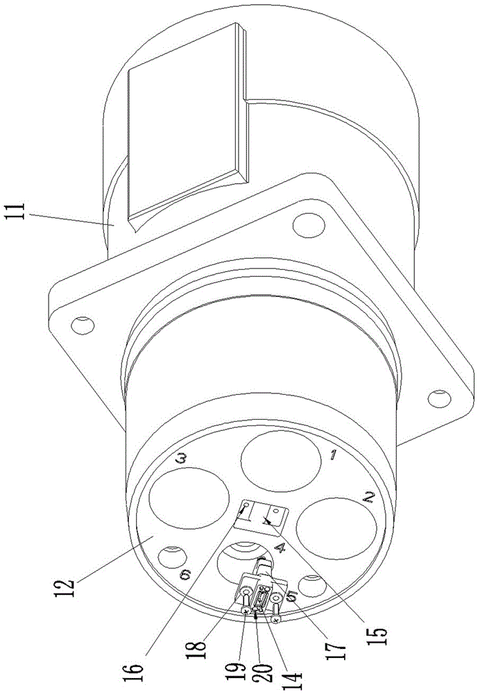
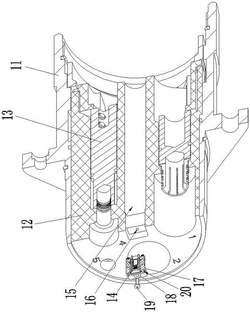
[0020] Embodiments of optoelectronic hybrid connector assemblies, such as Figure 1-8 As shown, the photoelectric hybrid connector assembly includes a plug and a socket.

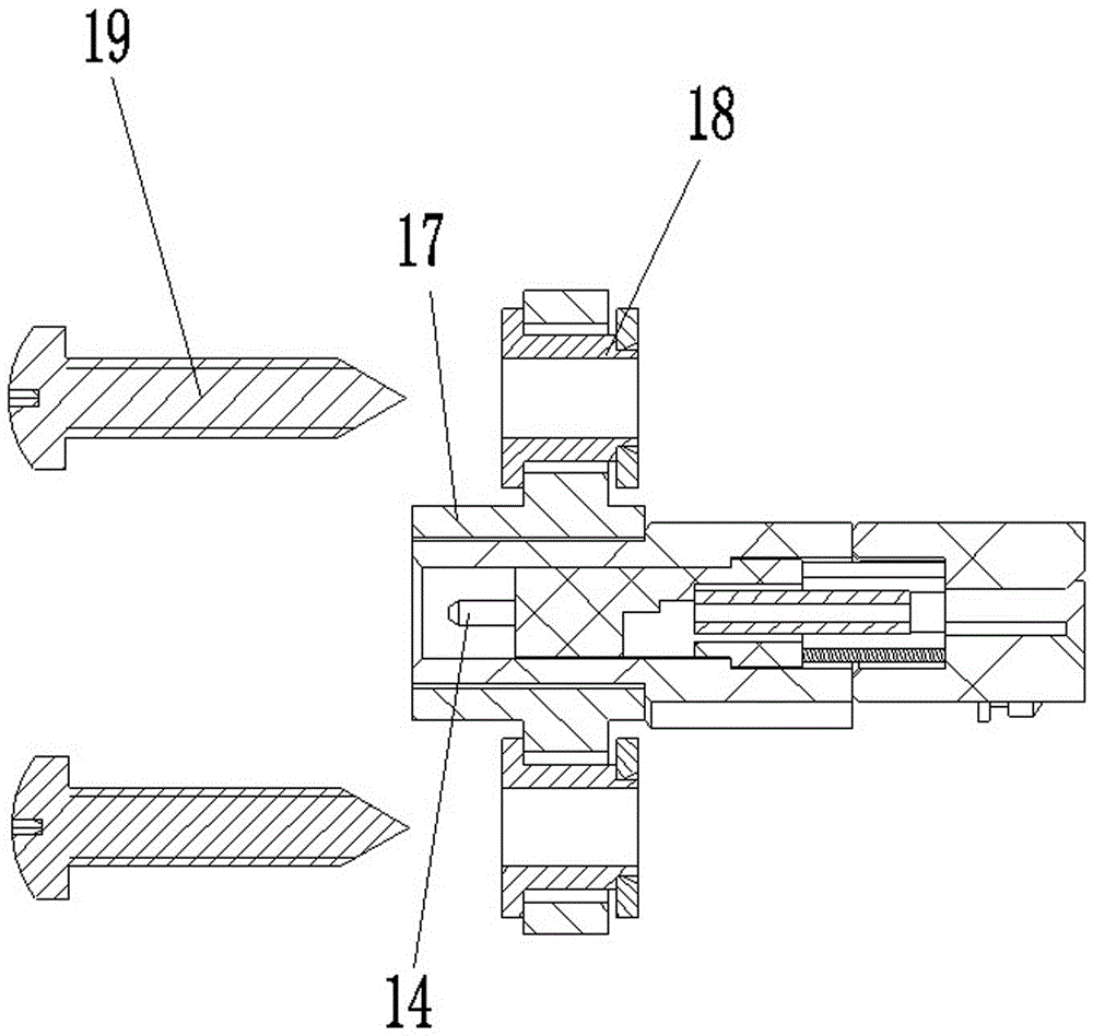
[0021] The structure of the plug is as Figure 1-4 As shown, it includes a housing 11 , an insulator 12 , an electrical contact 13 and an optical contact 14 .

[0022] The casing 11 is a mounting disk casing, and its structure is in the prior art, so it will not be repeated here.

[0023] The electrical contact 13 is fixedly mounted on the insulator 12. In this embodiment, the electrical contact 13 is a high-current contact, and its structure is in the prior art, so it will not be repeated here. In addition to being equipped with electrical contacts 13, an assembly hole 15 is also provided on the insulator 12, and the assembly hole 15 is used to assemble a corresponding optical connector. In this embodiment, the assembly hole 15 is surrounded by each electrical contact 13 The position between them is spec...


PUM


Abstract

The invention relates to the field of signal connectors, in particular to a photoelectric mixed-contact type connector module. The photoelectric mixed-contact type connector module comprises a plug and a socket, wherein the plug and the socket respectively comprises a housing, an insulation body and a contact part, the respective contact parts of the plug and the socket include optical contact parts and electrical contact parts, the optical contact parts of the plug and / or the optical contact part of the socket are contact parts of optical connectors assembled on the insulation bodies, and the optical connectors are assembled in installing holes formed in the corresponding insulation bodies. Due to the fact that the optical contact parts of the plug and / or the optical contact part are the contact parts of optical connectors assembled on the insulation bodies, the optical connectors are assembled in the installing holes formed in the corresponding insulation bodies, the optical contact parts are additionally assembled after the electrical contact parts are assembled during manufacture, the assembly position accuracy of the optical contact parts are easily ensured, and accordingly the problem of too high optical signal loss of the photoelectric mixed-contact type connector module can be solved.

Description

technical field [0001] The invention relates to the field of signal connectors, in particular to a photoelectric hybrid connector assembly. Background technique [0002] In recent years, with the continuous development and popularization of optical fiber transmission technology, more and more fields have begun to use optical fiber connectors, especially in some high-current electrical equipment, the application range of optical fiber transmission technology is also expanding , with the emergence of some occasions that need to transmit both current signals and optical signals, photoelectric hybrid connectors emerged as the times require. [0003] As the name suggests, the photoelectric hybrid connector can not only transmit high-current signals as power transmission components, but also transmit optical signals as signal transmission components. The existing photoelectric hybrid connector includes a housing, an insulator assembled in the housing, and an electrical contact an...

Claims


Application Information

Patent Timeline
Patent Type & Authority Patents(China)
IPC IPC(8): G02B6/38
CPCG02B6/3817G02B6/3818G02B6/3879
Inventor 徐仁红
Owner CHINA AVIATION OPTICAL-ELECTRICAL TECH CO LTD
Why Eureka
Try Eureka