Mine channel wave signal wave-field separation method

A field separation and signal wave technology, applied in the field of trough wave exploration, can solve the problem of inaccurate separation results

Active Publication Date: 2015-06-03
HENAN POLYTECHNIC UNIV
View PDF6 Cites 13 Cited by
  • Summary
  • Abstract
  • Description
  • Claims
  • Application Information

AI Technical Summary

Problems solved by technology

[0006] The purpose of the present invention is to provide a mine channel wave signal wave field separation method to solve the problem of inaccurate separation results of the wave field separation method based on polarization filtering in the prior art

Method used


Image

  • Mine channel wave signal wave-field separation method
  • Mine channel wave signal wave-field separation method
  • Mine channel wave signal wave-field separation method

Examples


Embodiment Construction

[0054] The present invention will be further described in detail below in conjunction with the drawings.

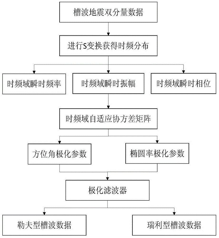
[0055] Such as figure 1 As shown, the basic steps of the method for separating the wave field of the mine channel wave signal in this scheme are as follows:

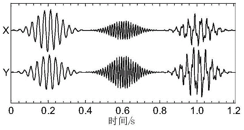
[0056] 1) Collect the horizontal component s of the groove wave signal x (t) and the vertical component of the slot wave signal s y (t), S transform the collected signal to get the spectrum ST during S transform x (t,f) and ST y (t,f);

[0057] 2) Use the time spectrum of S transform to obtain three parameters of instantaneous amplitude, instantaneous frequency and instantaneous phase, and use the parameters to construct the time-frequency domain adaptive covariance matrix MST(t, f);

[0058] 3) Calculate the eigenvalues ​​and eigenvectors of the time-frequency domain adaptive covariance matrix, and obtain the characteristic parameters of the slot wave polarization used to describe the vibration trajectory of the slot wave ...


PUM


Abstract

The invention relates to a mine channel wave signal wave-field separation method. An acquired channel wave signal is subjected to time frequency domain transformation to obtain a time frequency domain transformation time-frequency spectrum; a time frequency domain adaptive covariance matrix is structured; a distribution diagram of ellipticity and an azimuthal angle is obtained by feature values and feature vectors of the matrix; according to distribution features of the ellipticity and the azimuthal angle, filters for separating out different types of channel waves are structured to carry out filtering. The mine channel wave signal wave-field separation method has the benefits that only data of earthquake channel waves in the horizontal direction is analyzed, horizontal double-component earthquake wave data is subjected to time frequency domain transformation, the time frequency domain adaptive covariance matrix is structured, the distribution features of the ellipticity and the azimuthal angle, which are used for describing the size and the direction of a vibration track of a channel wave earthquake signal, are obtained, and the filters with different value ranges are structured to realize filtering on the collected channel wave data; compared with the prior art, the specific channel wave signal can be more rapidly, conveniently and accurately separated out, so that a mine stratum exploration effect is improved.

Description

Technical field [0001] The invention relates to the field of groove wave exploration, in particular to a method for polarization filtering and separating a mine groove wave signal. Background technique [0002] Channel wave seismic exploration methods include transmission wave method and reflected wave method. In the transmission method channel wave exploration, the Love type groove wave is mainly used. The Love type groove wave is a linearly polarized wave. The particle vibration direction is parallel to the coal layer, perpendicular to the wave propagation direction, and the movement track is linear; in the reflection method In channel wave exploration, Rayleigh channel waves are mainly used. Rayleigh channel waves are elliptical polarized waves. The particle vibration direction is perpendicular to the coal bed, parallel to the wave propagation direction, and the motion track is elliptical. In the actual collected groove wave data, due to the serious dispersion phenomenon, the...

Claims


Application Information

Patent Timeline
IPC IPC(8): G01V1/28
Inventor 冯磊张玉贵李晓斌李东会周明奂
Owner HENAN POLYTECHNIC UNIV
Why Eureka
Try Eureka