
A model box with high confining pressure loading system

A loading system and high confining pressure technology, which is applied in the direction of applying stable tension/pressure to test the strength of materials, can solve the problem that the model box cannot simulate vibration experiments, etc., to reduce experimental costs, reduce self-weight, and facilitate disassembly and assembly. Effect

Active Publication Date: 2017-09-19
CHENGDU UNIVERSITY OF TECHNOLOGY
View PDF8 Cites 0 Cited by
  • Summary
  • Abstract
  • Description
  • Claims
  • Application Information

AI Technical Summary

Problems solved by technology

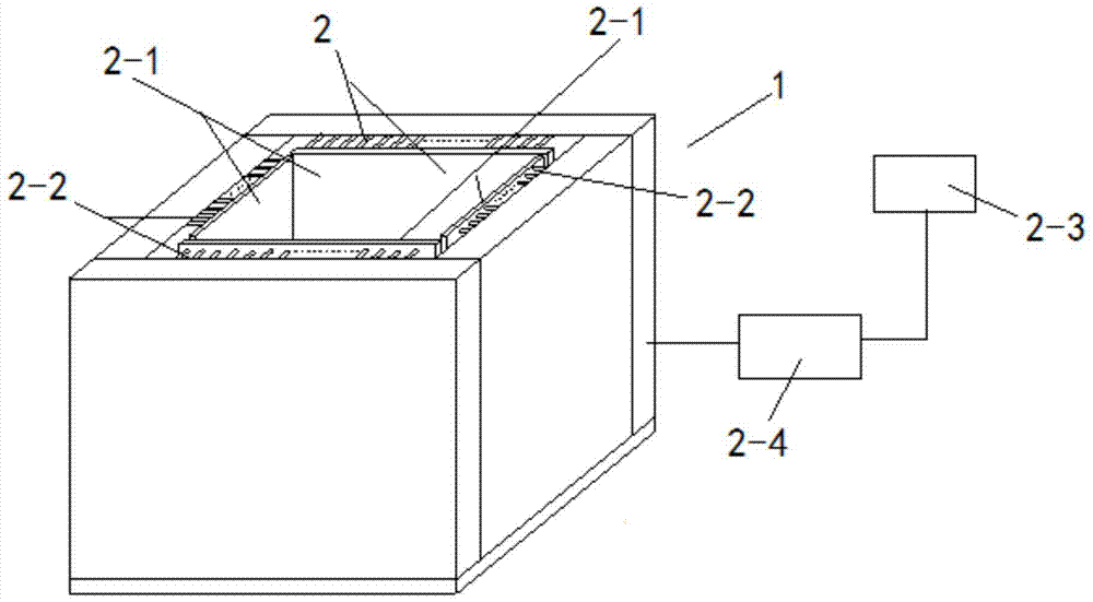
[0016] In order to solve the above problems, the present invention aims to provide a model box with a high confining pressure loading system; by further superimposing the high confining pressure simulation environment on the basis of the conventional vibration experiment simulation environment, the problem that the model box in the prior art cannot Technical Problems in Doing Simulated Vibration Experiments in High Confining Pressure Environment

Method used


Image

  • A model box with high confining pressure loading system
  • A model box with high confining pressure loading system
  • A model box with high confining pressure loading system

Examples


Embodiment 1

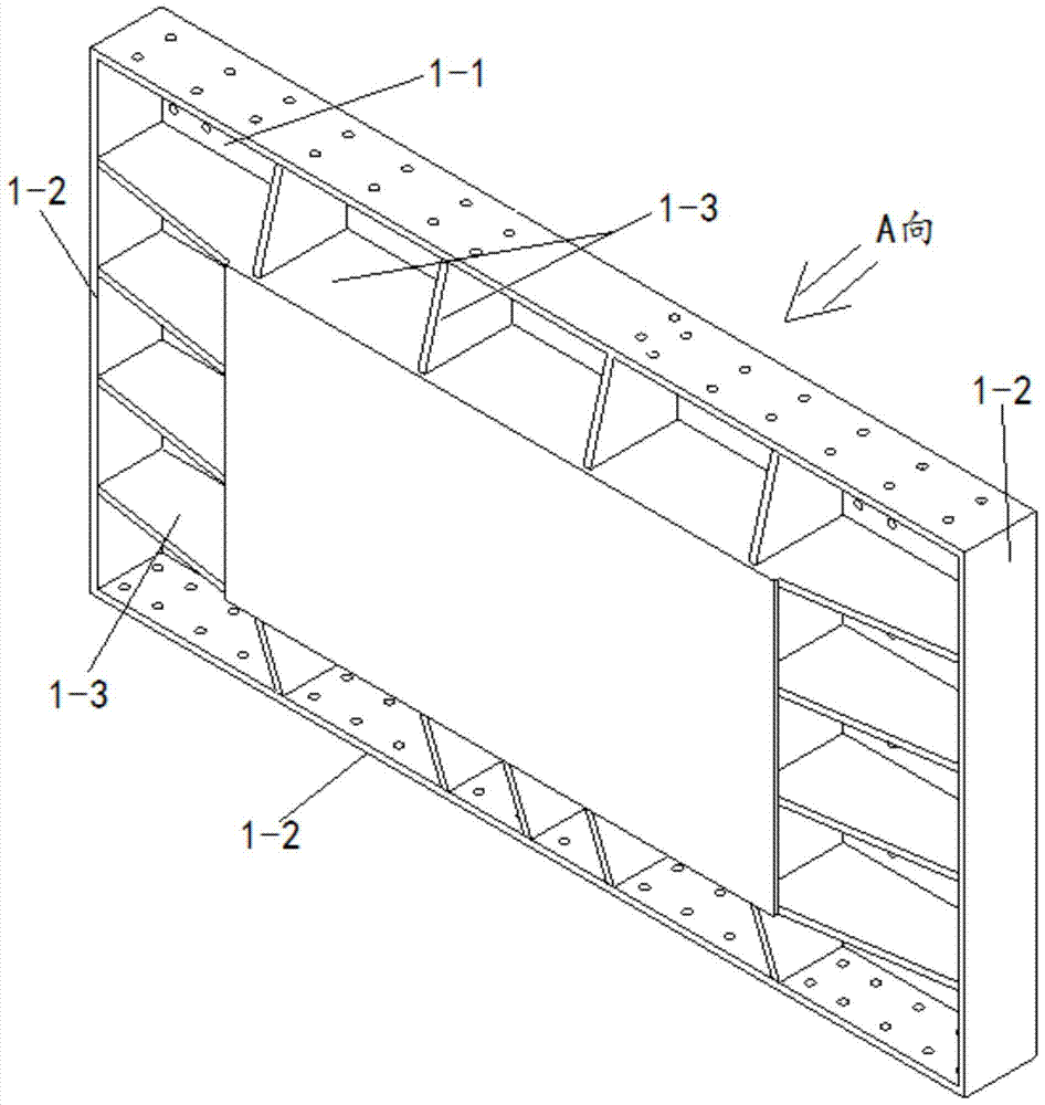
[0056] Considering the purpose and reference equipment, the model box is designed. The maximum volume size of the model box is 3m×2m×2m. The actual experiment needs to adjust the volume size of the inner cavity, the total weight is less than 8T, and the overall structure is as follows Figure 4 As shown, in order to make the box body structure more firm, the present invention is fastened with right-angle pull plate 1-4 and peripheral auxiliary supporting plate 1-5 at four right angles of the upper end surface of the model box, and the setting of right-angle pull plate helps After anchoring the lightweight and high-strength box wall after adjusting the size, the setting of the peripheral auxiliary support plate helps to feed back the load evenly to the experimental sample. In addition, the ribs of the light-weight and high-strength box wall of the present invention are designed in a window format. The design of the window-style rib structure can not only distribute the load eve...

Embodiment 2

[0061] Figure 8 As shown, in this embodiment, on the basis of Embodiment 1, a dowel bar CG is added between the oil cylinder and the baffle. Expand the scope of application of the present invention. In addition, the experiment shows that after the oil cylinder is loaded, the load can be fully transmitted to the baffle plate through the dowel rod, and then acted on the soil sample, which fully meets the experimental requirements. Furthermore, the use of the dowel bar can also greatly reduce the box loss of the model box. In the next test, only the baffle and the dowel bar need to be replaced, which reduces the cost of the experiment and is highly sustainable.

[0062] In order to further reduce the overall weight of the entire model box, the oil cylinder used in this embodiment is made of aluminum alloy, with a maximum stroke of 60mm, a rated operating pressure of 25MPa, and a maximum output of 4.9T. The front and rear baffles are each equipped with 88 oil cylinders, and the ...


PUM


Abstract

The present invention proposes a model box with a high confining pressure loading system; by further superimposing the high confining pressure simulation environment on the basis of the conventional vibration experiment simulation environment, it solves the problem that the model box in the prior art cannot be made in a high confining pressure environment Technical issues of simulated vibration experiments, the structure includes: box body, which is in the shape of a cuboid, and also includes: high confining pressure loading system; high confining pressure loading system includes: baffle, hydraulic cylinder integrated array, hydraulic pump station and console ; The inner wall of each side of the box is fastened to a baffle through the integrated array of hydraulic cylinders; the integrated array of hydraulic cylinders is connected to the oil circuit of the hydraulic pump station through the console.

Description

technical field [0001] The invention relates to the technical field of model boxes for geotechnical tests in geotechnical engineering, in particular to a model box with a high confining pressure loading system. Background technique [0002] Major geotechnical and tunnel projects often pass through areas with complex geology and landforms. The engineering properties of the surrounding rocks in these areas are uneven, and the faults, fractures, folds and other structures in the area are obviously developed, and the stress of the surrounding rocks is high. How to study the strength of rock and soil in these highly complex geological structure areas, and then ensure the safety of the project, is a problem that every engineer has to think carefully. For example, soft and hard rocks are widely distributed in the surrounding rocks of the newly built Erlangshan Tunnel. Faults and fractures are developed in the area, and the rock mass in the fault zone is broken. The tunnel will pa...

Claims


Application Information

Patent Timeline
Patent Type & Authority Patents(China)
IPC IPC(8): G01N3/10
Inventor 李天斌王刚方兴李育枢
Owner CHENGDU UNIVERSITY OF TECHNOLOGY
Learn More