
Specular suppression method based on sparse representation of strongly reflective surface-encoded light measurements

A technology of sparse expression and strong reflection, applied in measurement devices, optical devices, instruments, etc., can solve the problems of low extraction accuracy of fringe centers, changing the grayscale distribution of diffuse reflection fringes, and blurring of fringes, so as to improve the extraction accuracy. Effect

Inactive Publication Date: 2017-04-26
HARBIN UNIV OF SCI & TECH
View PDF6 Cites 0 Cited by
  • Summary
  • Abstract
  • Description
  • Claims
  • Application Information

AI Technical Summary

Problems solved by technology

[0003] The present invention aims to solve the problems of blurred stripes and partial information loss due to the influence of highlights in the prior art, changing the gray distribution of the original diffuse reflection stripes, and the low accuracy of stripe center extraction, and proposes a method based on sparse expression. Specular Suppression Method for Encoded Light Measurements on Strongly Reflecting Surfaces

Method used


Image

  • Specular suppression method based on sparse representation of strongly reflective surface-encoded light measurements
  • Specular suppression method based on sparse representation of strongly reflective surface-encoded light measurements
  • Specular suppression method based on sparse representation of strongly reflective surface-encoded light measurements

Examples


specific Embodiment approach 1

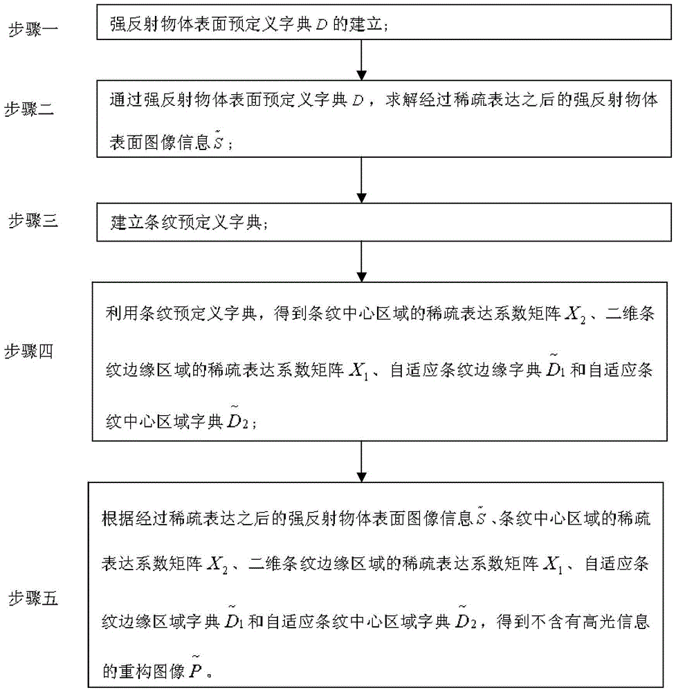
[0026] Specific implementation mode one: combine figure 1 To illustrate this embodiment, the highlight suppression method based on sparsely expressed strongly reflective surface coded light measurement is specifically carried out according to the following steps:

[0027] Step 1, the establishment of a predefined dictionary D on the surface of a strongly reflective object; Figure 8 , Figure 9 , Figure 10 , which illustrates the selection of the predefined dictionary on the surface of the object to be measured;

[0028] Step 2. Solve the image information of the surface of the strongly reflective object after sparse expression through the predefined dictionary D on the surface of the strongly reflective object like Figure 12 , which describes the surface information of the object the build process;

[0029] Step 3, establish a predefined dictionary of stripes;

[0030] Step 4. Use the stripe predefined dictionary to obtain the sparse expression coefficient matrix X...

specific Embodiment approach 2

[0032] Specific embodiment two: the difference between this embodiment and specific embodiment one is: the establishment of a predefined dictionary D on the surface of a strongly reflective object in the step one, the specific process is:

[0033] Strongly reflective objects have the characteristics of smooth surface and uneven surface brightness, while the two-dimensional Gabor function has anisotropy and multi-directionality, which can match the structure and content of the surface image of strongly reflective objects, and is immune to highlights, so the two-dimensional Gabor function is selected The dimensional Gabor function is used as the basis function of the predefined dictionary D on the surface of the strongly reflective object, and the basis function of the predefined dictionary D on the surface of the strongly reflective object is defined as follows:

[0034] The two-dimensional Gabor function is used as the base function of the predefined dictionary D on the surface...

specific Embodiment approach 3

[0053] Specific embodiment 3: The difference between this embodiment and specific embodiment 1 or 2 is that in the step 2, the dictionary D of the strongly reflective object surface is predefined to solve the image information of the strongly reflective object surface after sparse expression The specific process is:

[0054] 1) The OMP algorithm is used to match the predefined dictionary D of the surface of the strongly reflective object with the image information of the surface of the strongly reflective object, and the coefficient matrix A is obtained, then the image information S of the surface of the strongly reflective object can be expressed as:

[0055] S=AD;

[0056] The full name of the OMP algorithm is the Orthogonal Matching Pursuit algorithm, that is, the Orthogonal Matching Pursuit algorithm, which is a representative sparse expression approximation algorithm in the field of signal and image processing. Its basic idea is to select the column that best matches th...


PUM


Abstract

The invention discloses a highlight inhibition method for strong reflection surface encoding light measurement based on sparse expression, relates to a highlight inhibition method for strong reflection surface encoding light measurement, and aims to solve the problems that dim strips can be generated because of the influence of highlight, a part of information is lost, the gray level distribution of original diffuse reflection strips is changed and the strip center extraction accuracy rate is low in the prior art. The highlight inhibition method specially comprises the following steps: I, establishing a predefined dictionary D on the surface of a strong reflection object; II, acquiring image information shown in the description of the surface of the strong reflection object after sparse expression; III, establishing a strip predefined dictionary; IV, acquiring a sparse expression coefficient matrix X2 of a strip center area, a sparse expression coefficient matrix X1 of a two-dimensional strip edge area, a self-adaptive strip edge dictionary shown in the description, and a self-adaptive strip center area dictionary shown in the description; V, acquiring a reconstructed image without highlight information shown in the description. The highlight inhibition method can be applied to the field of highlight inhibition on the strong reflection surface in encoding light measurement.

Description

technical field [0001] The present invention relates to a method of highlight suppression for highly reflective surface coded light measurements. Background technique [0002] Since the 1970s, structured light three-dimensional measurement technology has been widely used and developed in high-speed detection, product development, quality control, reverse engineering and other fields due to its advantages of high precision, high efficiency and non-contact. Among them, the coding structure The optical method has high measurement efficiency and easy identification, which is the main development trend of structured light 3D measurement technology. When the coded structured light method is used for three-dimensional measurement, it is necessary to project stripes onto the surface of the measured object. The stripes carry the three-dimensional information of the object's surface profile. However, in practical applications, especially in industrial inspection, due to the influence ...

Claims


Application Information

Patent Timeline
Patent Type & Authority Patents(China)
IPC IPC(8): G01B11/25
Inventor 孙晓明于晓洋蔡瑛芙潘宗玮
Owner HARBIN UNIV OF SCI & TECH
Learn More